


31
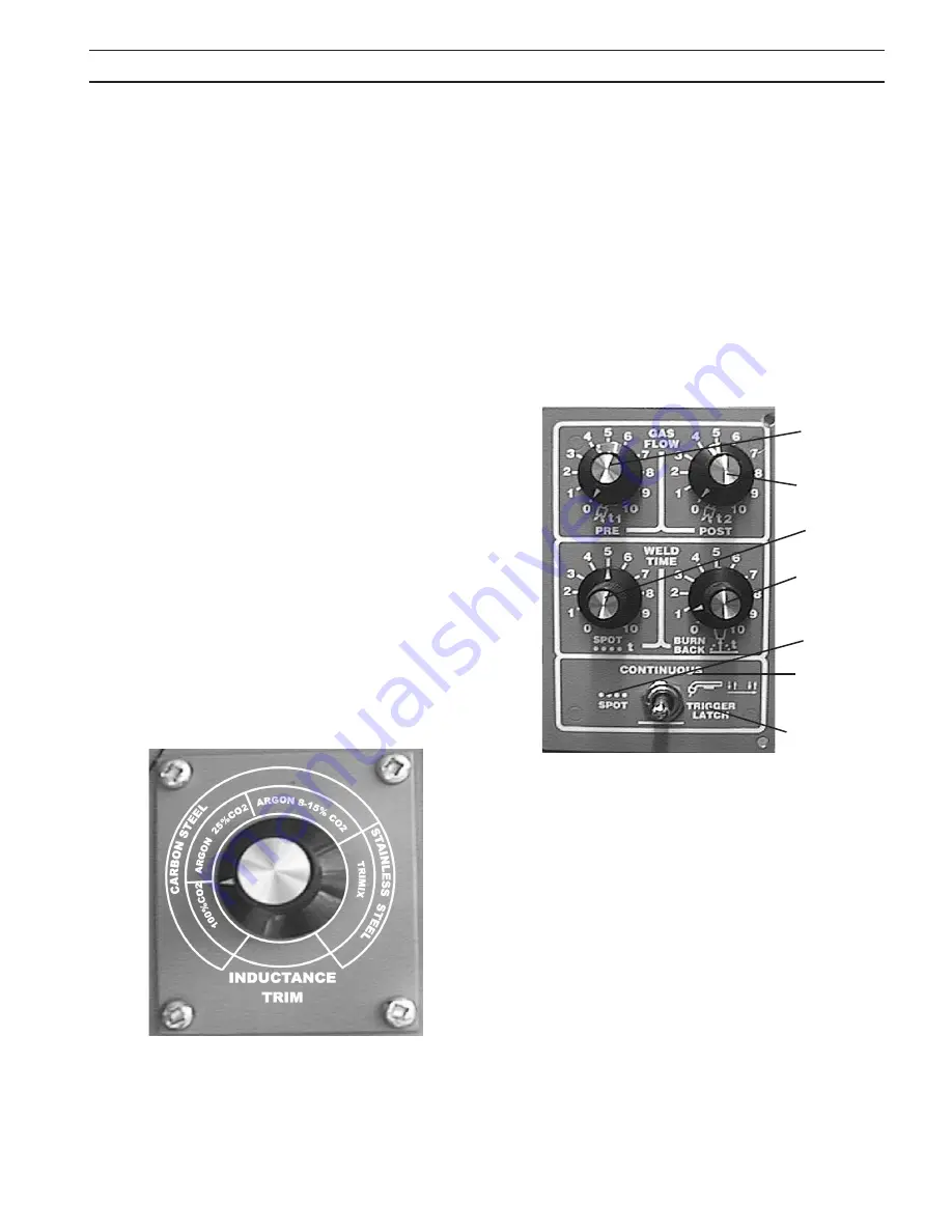
figure 14 - Inductance trim
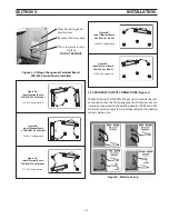
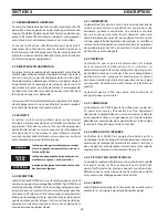
figure 15 - preflow/postflow/spot/Burnback
Continuous
“ON”
Trigger Latch
“ON”
Spot “ON”
Spot Time
Preflow
Time
Postflow Time
Burnback
Time
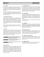
4.2 optIonal controls
4.2.1 InDuctance trIM (optIonal)
pn-0558002888 (figure 14)
Inductance is used to optimize short circuiting arc perfor-
mance by changing the current rise and fall time of each short
circuit. This results in improved spatter control, weld bead
wetting and arc stability. It is HIGHLY RECOMMENDED that
the Inductance Trim option be used for optimum short arc
welding performance with stainless steel wires.
The INDUCTANCE TRIM is installed inside the wire spool com-
partment, above the wire feed motor, to the left of the Burn-
back adjustment. The “easy to set” dial is calibrated by wire
alloy (Carbon Steel and Stainless Steel) and Shielding gas:
100% CO
2
Argon - 25% CO
2
Argon - 8 to 15% CO
2
Trimix (Stainless Helium Mixtures)
The short circuiting Mig arc performance will change from
a high short circuit frequency, fast reacting arc, to a lower
short circuit frequency, soft and less spattering arc as the
dial is turned clockwise. The optimized arc performances
will vary depending on shielding gas, wire diameter and
alloy. Gases and alloys other than those indicated can also
be optimized with this control. The operator can adjust this
control as desired to optimize personal preferences of weld-
ing characteristics.
(optIonal) pn-0558002889 (figure 15)
This optional control is mounted in place of the standard
burnback control inside the wire spool compartment. A
description of the module follows:
A. Preflow/Postflow - The PREFLOW control sets the time of
the preflow shielding gas before the wire starts feeding
(0-1.5 sec.). The POSTFLOW control sets the time the
shielding gas remains “ON” after the arc is turned “OFF”
(0-7.5 sec.).
B. Spot Weld Time - This dial sets the spot weld time from 0 to
5 seconds and is controlled by a current detect switch.
The timer does not start until current is detected to insure
consistent results.
C. Burnback Control - See 4.1.11
D. Spot Weld Switch Position - With the toggle switch in the
SPOT (left) position, the SPOT timer is turned “ON”, and
the spot weld time is controlled by the SPOT WELD TIMER
dial.
E. Continuous Position - With the toggle switch in the CON-
TINUOUS (center) position, the welding continues as long
as the Mig gun trigger is depressed.
F. Trigger Lock Position - With the toggle switch in the
TRIGGER LOCK (right) position, the welding process begins
when the gun trigger is depressed. Once the welding
process has started, the gun trigger may be released with-
out affecting the welding process. To stop the welding
operation, the gun trigger must be depressed a second
time. This allows a continuous weld without having to
continuously depress the gun trigger.
sectIon 4
operatIon
4.2.2 prefloW/postfloW/spot/BurnBacK
Summary of Contents for Multimaster 300
Page 1: ...Multimaster300 300X MIG TIG STICK WELDING PACKAGE 0558007770 06 2010 Instruction Manual...
Page 4: ...4 table of contents...
Page 40: ...40 TABLE DES MATI RES...
Page 66: ...66 section 6 replacement parts...
Page 67: ...67 section 6 replacement parts 26...
Page 68: ...68 section 6 replacement parts...
Page 69: ...69 section 6 replacement parts...
Page 70: ...70 section 6 replacement parts...
Page 71: ...71 section 6 replacement parts...
Page 72: ...72 section 6 replacement parts...
Page 73: ...73 section 6 replacement parts...
Page 74: ...74 section 6 replacement parts...
Page 75: ...75 section 6 replacement parts...
Page 76: ...76 section 6 replacement parts Mulitmaster 300 Mulitmaster 300X...
Page 77: ...77 section 6 replacement parts Mulitmaster 300 Mulitmaster 300X...
Page 78: ...78 section 6 replacement parts Mulitmaster 300 Mulitmaster 300X...
Page 79: ...79 section 6 replacement parts Mulitmaster 300 Mulitmaster 300X...
Page 80: ...80 section 6 replacement parts Mulitmaster 300 Mulitmaster 300X...
Page 81: ...81 section 6 replacement parts Mulitmaster 300 Mulitmaster 300X...
Page 84: ...section 6 replacement parts...


