background image

32

sectIon 3   


                         operatIon

note

On many CV power sources the actual welding arc voltage is usually less the “Open Circuit Voltage” (OCV) set on the power 

source front panel.  Therefore, an extra 3 to 6 volts should be added to the power source front panel setting to achieve the 

“actual” arc voltage needed or shown in the tables.

* MobileFeed Wire Feed Speed Knob Position

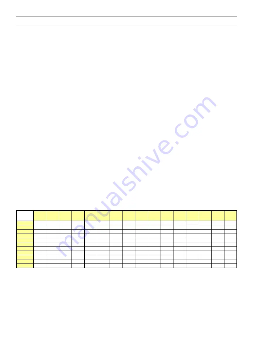
WIRE FEED SPEED TABLE

WFS

Set

19 V

20 V

21 V

22 V

23 V

24 V

25 V

26 V

27 V

28 V

29 V

30 V

31 V

32 V

33 V

34 V

Min

0

0

0

0

0

0

0

0

0

0

0

0

0

0

0

0

1

4

5

5

6

6

7

7

7

9

11

12

15

14

13

13

11

2

44

51

56

65

70

74

77

85

90

93

95

103

102

102

101

100

3

99

109

116

129

136

140

144

155

165

173

179

196

198

200

201

205

4

152

163

170

184

196

204

211

230

241

250

256

275

282

287

291

302

5

210

225

235

255

270

281

290

315

329

339

347

370

379

385

390

405

6

267

282

292

312

331

345

356

388

412

430

443

483

490

495

499

510

7

334

354

368

395

415

430

441

475

503

524

540

587

594

599

603

615

8

380

411

431

472

494

511

523

560

589

610

626

675

685

693

698

715

9

385

427

454

510

536

556

571

615

649

674

693

750

770

785

796

830

Max

395

435

462

515

544

565

581

630

667

695

716

779

803

820

833

873

Min

Max

* Wire 

Speed Set

3.5  shutDoWn

A.  Release torch trigger to break the arc.

B.  When leaving the equipment unattended, always shut OFF and disconnect all power to the equipment and shut off the 

shielding gas supply at source.

MobileFeed 300 with Digital meter and

CONSTANT CURRENT Power Source

Using the table, select the weld VOLTAGE / CURRENT 

1. 

needed for the wire type and diameter to be weld-

ed.
Set  the  power  supply  CURRENT  using  the  cur-

2. 

rent  control  knob  on  the  front  panel  of  the  power 

source.
Read the WIRE FEED SPEED (WFS) at the top of the 

3. 

column for the wire type, diameter and weld VOLT-

AGE / CURRENT chosen.
Flip the MobileFeed digital display switch to the WFS 

4. 

position.
Release the pressure roll assembly and pull the gun 

5. 

trigger then set the WFS on the digital display using 

the VOLTS / WFS knob.
Reset  the  pressure  roll  assembly  and  strike  an  arc 

6. 

then trim the arc length as needed using the VOLTS 

/ WFS knob. 

MobileFeed 300 with Digital meter and

CONSTANT VOLTAGE Power Source

Using the table, select the weld VOLTAGE / CURRENT 

1. 

needed for the wire type and diameter to be weld-

ed.
Set the power supply VOLTAGE using the voltage con-

2. 

trol knob on the front panel of the power source.
Read the WIRE FEED SPEED (WFS) at the top of the 

3. 

column for the wire type, diameter and weld VOLT-

AGE / CURRENT chosen.
Flip the MobileFeed digital display switch to the WFS 

4. 

position.
Release the pressure roll assembly and pull the gun 

5. 

trigger then set the WFS on the digital display using 

the VOLTS / WFS knob.
Reset  the  pressure  roll  assembly  and  strike  an  arc 

6. 

then trim the arc length as needed using the VOLTS 

/ WFS knob.

note

Using the “Constant Feed” dip switch settings when using a CC power source is NOT RECOMMENDED.  Extreme wire feed 

speed sensitivity exists making it difficult to set stable welding condition.  The arc stability is very dependant on maintain-

ing constant TTW distance which is almost impossible to control when welding manually.  “Constant Speed” settings is only 

recommended for use with CV power sources.

Typical welding voltages for 5000 Aluminum are between 21 and 25 volts which limits the wire feed speed of the Mobile-

Feed especially if trying to weld with 035” diameter 5356 alloy.  Welding with wire diameters ≤3/64” and/or below 22 arc 

volts could cause problems with limited wire feed speed and the inability to achieve a good welding condition.

Summary of Contents for MobileFeed 300 AVS

Page 1: ...MobileFeed 300 AVS Portable Off The Arc Wire Feeder Instruction Manual 0558005921 03 2008 ...

Page 2: ...from improper use faulty maintenance damage improper repair or alteration by anyone other than the manufacturer or a ser vice facility designated by the manufacturer Be sure this information reaches the operator You can get extra copies through your supplier These INSTRUCTIONS are for experienced operators If you are not fully familiar with the principles of operation and safe practices for arc we...

Page 3: ......

Page 4: ...4 ...

Page 5: ...PERATION 27 3 1 Controls 27 3 1 1 Power Switch 27 3 1 2 Wire Feed Speed Arc Voltage Control 27 3 1 3 Wire Feed Speed Constant Speed 27 3 2 Operating Procedures 29 3 2 1 Operating Safety Precautions 29 3 3 Changing Meter Display IPM to MPM 30 3 4 Setting A Welding Procedure 31 3 5 Shutdown 32 SECTION 4 MAINTENANCE 33 4 1 Maintenance 33 4 2 Inspection and Service 33 4 2 1 Wire Feeder 33 4 2 2 Soleno...

Page 6: ...6 TABLE OF CONTENTS ...

Page 7: ... 5 Protect other personnel from arc rays and hot sparks with a suitable non flammable partition or curtains 6 Usegogglesoversafetyglasseswhenchippingslag orgrinding Chippedslagmaybehotandcanflyfar Bystanders should also wear goggles over safety glasses FIRES AND EXPLOSIONS Heat from flames and arcs can start fires Hot slagorsparkscanalsocausefiresand explosions Therefore 1 Remove all combustible m...

Page 8: ...posuretoEMFmayhaveotherhealtheffectswhich are unknown 3 Welders should use the following procedures to minimize exposure to EMF A Route the electrode and work cables together Secure them with tape when possible B Never coil the torch or work cable around your body C Do not place your body between the torch and work cables Route cables on the same side of your body D Connecttheworkcabletotheworkpie...

Page 9: ...able from Compressed Gas Association 1235 Jefferson Davis Highway Arlington VA 22202 EQUIPMENT MAINTENANCE Faulty or improperly maintained equipment can cause injury or death Therefore 1 Alwayshavequalifiedpersonnelperformtheinstal lation troubleshooting and maintenance work Do not perform any electrical work unless you are qualified to perform such work 2 Before performing any maintenance work in...

Page 10: ...e Practices for Welding and Cutting of Containers That Have Held Hazardous Substances Meaning of symbols As used throughout this manual Means Atten tion Be Alert Your safety is involved Meansimmediatehazardswhich if not avoided will result in im mediate serious personal injury or loss of life Means potential hazards which could result in personal injury or loss of life Meanshazardswhichcouldresult...

Page 11: ...l arco y chis pascalientesconunacortina adecuadano flamable como división 6 Usecaretaprotectoraademásdesusgafasdesegu ridad cuando esté removiendo escoria o puliendo La escoria puede estar caliente y desprenderse con velocidad Personas cercanas deberán usar gafas de seguridad y careta protectora FUEGO Y EXPLOSIONES El calor de lasflamasyelarco puedenocacionar fuegos Escoria caliente y las chispas ...

Page 12: ...ponerseacamposelectromagnéticos EMF puede causar otros efectos de salud aún desconocidos 3 Los soldadores deberán usar los siguientes proced imientos para minimizar exponerse al EMF A Mantenga el electrodo y el cable a la pieza de trabajo juntos hasta llegar a la pieza que usted quiere soldar Asegúrelos uno junto al otro con cinta adhesiva cuando sea posible B Nunca envuelva los cables de soldar a...

Page 13: ...NTO DEL EQUIPO Equipo defectuoso o mal mantenido puede causar daño o muerte Por lo tanto 1 Siempre tenga personal cualificado para efec tuar l a instalación diagnóstico y mantenimiento del equipo No ejecute ningún trabajo eléctrico a menos que usted esté cualificado para hacer el trabajo 2 Antes de dar mantenimiento en el interior de la fuente de poder desconecte la fuente de poder del suministro ...

Page 14: ...té Alerta Se trata de su seguridad Significa riesgo inmediato que de no ser evadido puede resultar inmediatamente en serio daño personal o la muerte Significa el riesgo de un peligro potencial que puede resultar en serio daño personal o la muerte Significa el posible riesgo que puede resultar en menores daños a la persona ...

Page 15: ...ection Ils récapitulent les informations de précaution provenant des références dans la section des Informations de sécurité supplémentaires Avant de procéder à l installation ou d utiliser l unité assurez vous de lire et de suivre les précautions de sécurité ci dessous danslesmanuels lesfichesd informationsurla sécuritédumatérieletsurlesétiquettes etc Toutdéfaut d observer ces précautions de sécu...

Page 16: ...onsultez ANSI ASC Standard Z49 1 à la page suivante pour des recommandations spécifiques concernant la ventilation 1 Assurez vous que le châssis de la source d alimentation est branché au système de mise à la terre de l alimentation d entrée 2 Branchez la pièce à traiter à une bonne mise de terre électrique 3 Branchez le câble de masse à la pièce à traiter et assurezunebonneconnexionafind éviterle...

Page 17: ...gaz contenant des chimiques consid éres par l état de la Californie comme étant une cause des malformations congénitales et dans certains cas du cancer California Health Safety Code 25249 5 et seq MANIPULATION DES CYLINDRES La manipulation d un cylindre sans observerlesprécautionsnécessaires peut produire des fissures et un échappement dangereux des gaz Unebrisuresoudaineducylindre delasoupapeou d...

Page 18: ...ez vigilant Votre sécurité est en jeu Signifie un danger immédiat La situation peut entraîner des blessures graves ou mortelles Signifieundangerpotentielquipeutentraînerdes blessures graves ou mortelles Signifieundangerquipeutentraînerdesblessures corporelles mineures DANGER AVERTISSEMENT ATTENTION ...

Page 19: ...Meets lEC 974 1 specifications Ordering Information Each MobileFeed wire feeder includes gas solenoid and dual groove feed rolls and digital meter MobileFeed 300 AVS LC40 0558005729 MobileFeed 300 AVS LC40 Push Pull 0558005745 Includes 045 1 16 in 1 2 1 6 mm serrated groove drive rolls MobileFeed 300 AVS OKC CE 0558005728 MobileFeed 300 AVS OKC Push Pull CE 0558005832 Includes 035 045 in 0 9 1 2 m...

Page 20: ...78 1 0558001757 1 0558001758 1 040 in 1 0 mm V Groove 0369 557 003 2 0558001078 1 0558001757 1 0558001758 1 045 in 1 2 mm V Groove 0369 557 003 2 0558001078 1 0558001757 1 0558001758 1 045 in 1 2 mm V Groove X2 0369 557 010 2 0558001078 1 0558001757 1 0558001758 1 052 in 1 4 mm V Groove 0369 557 013 2 0558001079 1 0558001757 1 0558001758 1 062 in 1 6 mm V Groove 0369 557 013 2 0558001079 1 0558001...

Page 21: ...ment 1 2 RECEIVING HANDLING Prior to installing this equipment clean all packing mate rial from around the unit and carefully inspect for any damage that may have occurred during shipment Any claimsforlossordamagethatmayhaveoccurredintransit must be filed by the purchaser with the carrier A copy of the bill of lading and freight bill will be furnished by the carrier on request if occasion to file ...

Page 22: ...22 SECTION 1 DESCRIPTION ...

Page 23: ...nstall proper guide tubes D Reverse or replace drive rolls with the required size designation which is imprinted on the side of the roll facing out E Replace the screw removed in Step B and tighten F Thread the wire and secure the pressure roll assem bly 2 2 WELDING WIRE INSTALLATION Install a spool of welding wire on the hub as follows A Turn the red spool retainer in the hub as shown in picture ...

Page 24: ...rt turning when the torch trigger is pressed 5 If using gas shielded wires adjust the gas flow meter to the desired flow rate by closing the gun trigger switch 6 TurnpowersourceandwirefeederOFFwhennot in use 2 3 TORCH CONNECTIONS The torch adaptor on the MobileFeed connects directly to the wire feeder wire drive assembly power and shield ing gas supply Line up the torch connector with the wire fee...

Page 25: ...ionshouldprovideenoughdragtokeepthe wire spool from spinning freely after the wire feed stops Thebrakehubisadjustedwhendelivered ifreadjustment isrequired followtheinstructionsbelow Adjustthebrake hub so that wire is slightly slack when wire feed stops Adjusting the braking torque Turn the red handle to the locked position Insert a screwdriver into the springs in the hub Turn the springs clockwise...

Page 26: ...26 SECTION 2 INSTALLATION ...

Page 27: ...age Turning the wire feed speed dial clockwise decreases arc voltage turning itcounterclockwiseincreasesarcvoltage Theactualwirefeed speed for any given setting varies with the arc voltage In creasing arc voltage causes an increase in wire feed speed The MobileFeed 300 AVS wire feeder is equipped with au tomatic Slow wire run in If the wire feeder senses that the power source output voltage is in ...

Page 28: ... stick out wire density or shielding variations will cause the wire feed speed to compensate to maintain the arc length preset Alternate Setting Constant Voltage Operation Constant Wire Feed Speed In this operation mode the feeder is ready for connection to Constant Voltage power source which is typically used for most GMAW MIG MAG welding CV power sources provide high short circuit currents for g...

Page 29: ... and perchlorethylene to form phosgene even when these vapors are present in low concentrations DO NOT weld where chlorinated solvents are present in atmospheres in or around the arc C DONOTtouchtheelectrode contacttipormetalparts when power is ON all are electrically energized HOT and can cause a possibly fatal shock DO NOT allow electrode to touch grounded metal It will create an arc flash that ...

Page 30: ...gital meter board These switches can be set up for meter to read in inches per minute IPM or in meters per minute MPM as shown below The meter is factory set in IPM positions Set the switch on the digital meter to the desired mode of operation If the IPM mode is selected the meter will read the PRE SET wire speed when not feeding wire and the ACTUAL wire speed when feeding wire If the VOLTS mode i...

Page 31: ...0 25 180 25 200 26 215 27 230 28 245 25 260 26 280 27 300 26 290 27 340 30 400 28 320 30 340 25 110 25 140 26 150 26 190 26 200 23 260 30 300 32 350 27 205 27 220 22 100 23 150 23 175 24 190 25 205 25 220 23 200 25 250 27 280 27 290 28 340 32 300 32 350 39 500 ARC VOLTS AMPS WELD CURRENT WIRE FEED SPEED IPM WIRE DIAMETER FLUX CORE E70T 1 2 METAL CORE STEEL SOLID WIRE AL Si ALUMINUM AL Mg ALUMINUM ...

Page 32: ...IRE FEED SPEED WFS at the top of the 3 column for the wire type diameter and weld VOLT AGE CURRENT chosen Flip the MobileFeed digital display switch to theWFS 4 position Release the pressure roll assembly and pull the gun 5 trigger then set the WFS on the digital display using the VOLTS WFS knob Reset the pressure roll assembly and strike an arc 6 then trim the arc length as needed using the VOLTS...

Page 33: ...tors enter Equipment Theelectrodewireandallmetalpartsincontactwithitare electrically energized while welding Inspect these parts periodically for defective insulation and other electrical hazards If uninsulated cable and parts are not replaced an arc caused by a bared cable or part touching a grounded surface may damage unprotected eyes or start a fire Body contact with a bared cable connector or ...

Page 34: ...er supply power source wire feeder or wire guide train casing drive rolls liners and con tact tip If this inspection indicates trouble in the wire feeder refer to the following pages Schematic Diagram and or Wiring Diagram Many troubleshooting situations require that the power remain on and that power terminals in the equipment carry voltage Exercise extreme caution whenworkingon live equipment Av...

Page 35: ...35 SECTION 4 MAINTENANCE ...

Page 36: ...36 SECTION 4 MAINTENANCE ...

Page 37: ...f non ESAB parts may void your warranty Replacement parts may be ordered from your ESAB Distributor Be sure to indicate any special shipping instructions when ordering replacement parts Refer to the Communications Guide located on the back page of this manual for a list of customer service phone numbers 5 2 Ordering Bill of material items that have blank part numbers are provided for customer info...

Page 38: ...38 SECTION 5 REPLACEMENT PARTS ...

Page 39: ...39 SECTION 5 REPLACEMENT PARTS ...

Page 40: ...40 SECTION 5 REPLACEMENT PARTS ...

Page 41: ...41 SECTION 5 REPLACEMENT PARTS ...

Page 42: ...SECTION 5 REPLACEMENT PARTS ...

Page 43: ...SECTION 5 REPLACEMENT PARTS ...

Page 44: ...SECTION 5 REPLACEMENT PARTS ...

Page 45: ...SECTION 5 REPLACEMENT PARTS ...

Page 46: ...46 SECTION 5 REPLACEMENT PARTS ...

Page 47: ...d Screw Thumb M6X12 Pressure Arm Bogie Pressure Roll Axle Pressure Roll Locating Pin Nut Pressure Roll Axle Circlip Retaining Screw Pressure Arm Spring Bogie Auto Lift Spring to Pressure Arm Auto Lift Spacer Tube Small Spacer Tube Big Spacer Tube Pressure Arm Auto Lift DESCRIPTION Spacer Tube Bogie Axle Pressure Arm Allen Screw Gear Adaptor Feed Roll Axle Gear Adaptor Feed Roll Washer Retaining Sc...

Page 48: ...SECTION 5 REPLACEMENT PARTS ...

Page 49: ... inputs 07 2006 Updated per Joe DeVito inputs 10 2006 Updated pictures and updated Replacement Parts subsection 04 2007 Updated Drive Roll and Guide Tube table in Section 1 per Mike Palumbo inputs 03 2008 Updated pictures and updated Replacement Parts section per CN 083002 ...

Page 50: ...ax 843 664 5557 Hours 7 30 AM to 3 30 PM EST Repair Estimates Repair Status F WELDING EQUIPMENT TRAINING Telephone 843 664 4428 Fax 843 679 5864 Hours 7 30 AM to 4 00 PM EST Training School Information and Registrations G WELDING PROCESS ASSISTANCE Telephone 800 ESAB 123 Hours 7 30 AM to 4 00 PM EST H TECHNICAL ASST CONSUMABLES Telephone 800 933 7070 Hours 7 30 AM to 5 00 PM EST IF YOU DO NOT KNOW...

Page 51: ......

Page 52: ......

Reviews: