background image

6

SeCTION 1 

SAFeTY PReCAUTIONS

  1.  Be sure the power source frame (chassis) is con-

nected to the ground system of the input power.

  2.  Connect  the  workpiece  to  a  good  electrical 

ground.

  3.  Connect the work cable to the workpiece. A poor 

or missing connection can expose you or others 

to a fatal shock.

  4.  Use well-maintained equipment. Replace worn or 

damaged cables.


  5.  Keep  everything  dry,  including  clothing,  work 

area,  cables,  torch/electrode  holder,  and  power 

source.

  6.  Make sure that all parts of your body are insulated 

from work and from ground.

  7.  Do not stand directly on metal or the earth while 

working in tight quarters or a damp area; stand 

on dry boards or an insulating platform and wear 

rubber-soled shoes.

  8.  Put on dry, hole-free gloves before turning on the 

power.

  9.  Turn off the power before removing your gloves.

 10.  Refer  to  ANSI/ASC  Standard  Z49.1  (listed  on 

next page) for specific grounding recommenda-

tions. Do not mistake the work lead for a ground 

cable.

eleCTRIC  AND  MAGNeTIC  FIelDS 

— May be dangerous. electric cur-

rent  flowing  through  any  conduc-

tor  causes  localized  electric  and 

Magnetic Fields (eMF). Welding and 

cutting current creates eMF around welding cables 

and welding machines. Therefore:

1.  Welders having pacemakers should consult  their 

physician before welding. EMF may interfere with 

some pacemakers.

2.  Exposure to EMF may have other health effects which 

are unknown.

3.  Welders  should  use  the  following  procedures  to 

minimize exposure to EMF:

  A. Route the electrode and work cables together. 

Secure them with tape when possible.

  B.  Never coil the torch or work cable around your 

body.

  C. Do not place your body between the torch and 

work cables. Route cables on the same side of 

your body.

  D. Connect the work cable to the workpiece as close 

as possible to the area being welded.

  E.  Keep  welding  power  source  and  cables  as  far 

away from your body as possible.

FUMeS  AND  GASeS  --  Fumes  and 

gases, can cause discomfort or harm, 

particularly  in  confined  spaces.  Do 

not breathe fumes and gases. Shield-

ing  gases  can  cause  asphyxiation. 

Therefore:

1.  Always provide adequate ventilation in the work area 

by natural or mechanical means. Do not weld, cut, or 

gouge on materials such as galvanized steel, stain-

less steel, copper, zinc, lead, beryllium, or cadmium 

unless positive mechanical ventilation is provided. 

Do not breathe fumes from these materials.

2.  Do not operate near degreasing and spraying opera-

tions. The heat or arc rays can react with chlorinated 

hydrocarbon    vapors  to  form  phosgene,  a  highly 

toxic gas, and other irritant gases.

3.  If you develop momentary eye, nose, or throat ir-

ritation while operating, this is an indication that 

ventilation  is  not  adequate.  Stop  work  and  take 

necessary steps to improve ventilation in the work 

area. Do not continue to operate if physical discom-

fort persists.

4.  Refer to ANSI/ASC Standard Z49.1 (see listing below) 

for specific ventilation recommendations.

Summary of Contents for MIG 4HD

Page 1: ...BALANCED BOOM MIG 4HD DURADRIVE ARISTODRIVE 4 48 0558004214 09 2006 Installation Manual ...

Page 2: ...ll perform in conformity with the description thereof contained in this manual and accompanying labels and or inserts when installed operated maintained and repaired in accordance with the instructions provided This equipment must be checked periodically Malfunctioning or poorly maintained equipment should not be used Parts that are broken missing worn distorted or contaminated should be replaced ...

Page 3: ...ge FHD 17 3 3 Installation of the Power Input Cable Assembly 17 3 4 Installation of the Control Cable Assembly 18 3 5 Installation of the Gas Hose 18 3 6 Installation of the Electrode Conduit 18 3 7 Installation of the 2 Spindle Assembly 14 3 8 Installation of the Electrode Weld Cable 18 3 9 Installation of the Wire Reel 18 3 10 Installation of the Gun Cable Assembly 19 3 11 Installation of the We...

Page 4: ... table of contents ...

Page 5: ...othing 5 Protect other personnel from arc rays and hot sparks with a suitable non flammable partition or curtains 6 Usegogglesoversafetyglasseswhenchippingslag orgrinding Chippedslagmaybehotandcanflyfar Bystanders should also wear goggles over safety glasses FIRES AND EXPLOSIONS Heat from flames and arcs can start fires Hot slagor sparks can also causefires and explosions Therefore 1 Remove all co...

Page 6: ...2 ExposuretoEMFmayhaveotherhealtheffectswhich are unknown 3 Welders should use the following procedures to minimize exposure to EMF A Route the electrode and work cables together Secure them with tape when possible B Never coil the torch or work cable around your body C Do not place your body between the torch and work cables Route cables on the same side of your body D Connecttheworkcabletothewor...

Page 7: ... available from Compressed Gas Association 1235 Jefferson Davis Highway Arlington VA 22202 EQUIPMENT MAINTENANCE Faulty or improperly maintained equipment can cause injury or death Therefore 1 Alwayshavequalifiedpersonnelperformtheinstal lation troubleshooting and maintenance work Do not perform any electrical work unless you are qualified to perform such work 2 Before performing any maintenance w...

Page 8: ... Safe Practices for Welding and Cutting of Containers That Have Held Hazardous Substances Meaning of symbols As used throughout this manual Means Atten tion Be Alert Your safety is involved Meansimmediatehazardswhich if not avoided will result in im mediate serious personal injury or loss of life Means potential hazards which could result in personal injury or loss of life Meanshazardswhichcouldre...

Page 9: ...os del arco y chis pascalientesconunacortina adecuadano flamable como división 6 Usecaretaprotectoraademásdesusgafasdesegu ridad cuando esté removiendo escoria o puliendo La escoria puede estar caliente y desprenderse con velocidad Personas cercanas deberán usar gafas de seguridad y careta protectora FUEGO Y EXPLOSIONES El calor de lasflamasyelarco puedenocacionar fuegos Escoria caliente y las chi...

Page 10: ... 2 Exponerseacamposelectromagnéticos EMF puede causar otros efectos de salud aún desconocidos 3 Los soldadores deberán usar los siguientes proced imientos para minimizar exponerse al EMF A Mantenga el electrodo y el cable a la pieza de trabajo juntos hasta llegar a la pieza que usted quiere soldar Asegúrelos uno junto al otro con cinta adhesiva cuando sea posible B Nunca envuelva los cables de sol...

Page 11: ...ENIMIENTO DEL EQUIPO Equipo defectuoso o mal mantenido puede cau sar daño o muerte Por lo tanto 1 Siempre tenga personal cualificado para efec tuar l a instalación diagnóstico y mantenimiento del equipo No ejecute ningún trabajo eléctrico a menos que usted esté cualificado para hacer el trabajo 2 Antes de dar mantenimiento en el interior de la fuente de poder desconecte la fuente de poder del sumi...

Page 12: ...ón Esté Alerta Se trata de su seguridad Significa riesgo inmediato que de no ser evadido puede resultar inmediatamente en serio daño personal o la muerte Significa el riesgo de un peligro potencial que puede resultar en serio daño personal o la muerte Significa el posible riesgo que puede resultar en menores daños a la persona ...

Page 13: ...ection Ils récapitulent les informations de précaution provenant des références dans la section desInformationsdesécuritésupplémentaires Avantde procéderàl installationoud utiliserl unité assurez vous de lire et de suivre les précautions de sécurité ci des sous dans les manuels les fiches d information sur la sécuritédumatérieletsurlesétiquettes etc Toutdéfaut d observer ces précautions de sécurit...

Page 14: ...ste 4 Consultez ANSI ASC Standard Z49 1 à la page suivante pour des recommandations spécifiques concernant la ventilation 1 Assurez vous que le châssis de la source d alimentation est branché au système de mise à la terre de l alimentation d entrée 2 Branchez la pièce à traiter à une bonne mise de terre électrique 3 Branchez le câble de masse à la pièce à traiter et assurezunebonneconnexionafind é...

Page 15: ... ou des gaz contenant des chimiques consi déresparl étatdelaCaliforniecomme étant une cause des malformations congénitales et dans certains cas du cancer California Health Safety Code 25249 5 et seq MANIPULATION DES CYLINDRES La manipulation d un cylindre sans observerlesprécautionsnécessaires peut produire des fissures et un échappement dangereux des gaz Unebrisuresoudaineducylindre delasoupapeou...

Page 16: ...n Soyez vigilant Votre sécurité est en jeu Signifie un danger immédiat La situation peut entraîner des blessures graves ou mortelles Signifieundangerpotentielquipeutentraînerdes blessures graves ou mortelles Signifieundangerquipeutentraînerdesblessures corporelles mineures DANGER AVERTISSEMENT ATTENTION ...

Page 17: ...lanced Boom 12 ft 4 48 FHD 0558003733 Balanced Boom 16 ft 4 48 FHD 0558003736 Balanced Booms SPLIT HEAVY DUTY SHD see Figure 2 3 Balanced Boom 8 ft 4 48 SHD 0558004009 Balanced Boom 10 ft 4 48 SHD 0558004012 Balanced Boom 12 ft 4 48 SHD 0558003442 Balanced Boom 16 ft 4 48 SHD 0558004011 Control Box to Power Source Cable Accessories Pallet Base Requires anchors or another method to secure base to f...

Page 18: ... Wirefeeder Mig 4HD Wirefeeder The complete Full Heavy Duty FHD boom package will be made up of the following Boom Wire Feeder Electrode Cable customer supplied Conduit Weld Wire Gas Hose Control Cable Plastic Trough optional Conduit Bushing Bracket Provisions to Mount 2 Spindle Assembly Feeder Mount Bracket Hardware ...

Page 19: ...DER BOOM SHOWING WIREFEEDER BRACKET PLACEMENT Figure 2 2 FULL HEAVY DUTY VERSION FHD Boom Mast Electrode Cable customer supplied Conduit Weld Wire Gas Hose Control Cable Conduit Bushing Bracket 2 Spindle Mount Assembly Bracket Feeder Mount Bracket ...

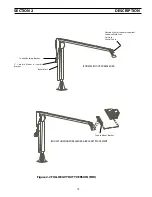
Page 20: ...age will be made up of the following Boom Wire Drive Assembly Control Box Assembly Electrode Cable customer supplied Conduit Weld Wire Gas Hose Control Cable to feed head Control Cable to power source Plastic Trough optional Conduit Bushing Bracket Provisions to Mount 2 Spindle Assembly Control Box Support Assembly Feeder Mount Bracket Hardware SECTION 2 DESCRIPTION ...

Page 21: ...ECTION 2 DESCRIPTION BOOM WITH CAGE CONTROL BOX BRACKET BOOM SHOWING WIREFEEDER CONTROL BOX PLACEMENT Figure 2 3 SPLIT HEAVY DUTY VERSION SHD Wire Drive Drive Box Feeder Mount Bracket Boom Mast Control Box ...

Page 22: ... SHD or FHD wire feeder boom package as follows 3 1 INSTALLATION OF THE SPLIT HEAVY DUTY PACKAGE SHD Wire Drive Drive Box mounted at end of boom arm control box mounted on boom mast A INSTALLING THE WIRE DRIVE DRIVE BOX ASSEMBLY Install the Wire Drive Drive Box Assembly using the 4 1 4 20 x 75 bolts with lock washers and nuts Mount the Wire Drive Drive Box Assembly at the end of the boom arm by li...

Page 23: ...hers After the Wire Feeder Assembly is in place completely tighten the bolts NOTE No cage will be used in this application 3 3 INSTALLATION OF THE POWER INPUT CABLE ASSEMBLY In FHD package the Power Input Cable Assembly will run from the power source to wire feeder assembly mounted on the end of the boom arm In the SHD package the power input cable assembly will run from the power source to the co...

Page 24: ...LY P N 948259 Install the 2 spindle assembly using the 4 5 16 dia bolts washers and nuts Place the larger washer into the spindle assembly before installation to the boom mast spindle bracket Line up the small hole on the spindle assembly with the roll pin on the mast After the 2 spindle assembly is in place completely tighten the bolt 3 4 INSTALLATION OF THE CONTROL CABLE ASSEMBLY SHD only Instal...

Page 25: ... 9 INSTALLATION OF THE WIRE REEL Load the wire reel with a coil of wire so as to dereel off the side of the coil closest to the conduit bushing Thread the wire through the entire length of conduit to the drive rolls to feed through the gun cable See 2 Spindle Assembly diagram 3 10 INSTALLATION OF THE GUN CABLE ASSEMBLY Install the gun cable assembly per manual provided with the torch 3 11 INSTALLA...

Page 26: ...rd 50 degrees to downward 6 degress 81 dia hole for 3 4 bolting 4 places BOOM DIMENSIONS NOMINAL BOOM LENGTH BOOM DIMENSION CHART A DIM B DIM 8 0 9 9 8 0 10 0 12 0 16 0 11 9 10 0 13 9 12 0 17 9 16 0 3 12 BOOM DIMENSION DIAGRAM C DIM 9 0 13 0 17 0 11 0 Friction Control Knob ...

Page 27: ...27 REVISION HISTORY Original release 15SEP06 ...

Page 28: ...rized Repair Stations Welding Equipment Troubleshooting C TECHNICAL SERVICE Telephone 800 ESAB 123 Fax 843 664 4452 Hours 8 00 AM to 5 00 PM EST Part Numbers Technical Applications Specifications Equipment Recommendations D LITERATURE REQUESTS Telephone 843 664 5562 Fax 843 664 5548 Hours 7 30 AM to 4 00 PM EST E WELDING EQUIPMENT REPAIRS Telephone 843 664 4487 Fax 843 664 5557 Hours 7 30 AM to 3 ...

Reviews: