ESAB HANDY PLASMA 125 Instruction Manual Download Page 10

10

a.

The duty cycle of this unit is 30% at rated out-
put current.  Duty cycle is based on a 10 minute
cycle; therefore, the unit can operate for a to-
tal of 3 minutes and shut off for cooling a total
of 7 minutes in a 10 minute period.

OPERATION

Wear the usual protective gloves, clothing and hel-
met. Helmet with filter lens shade No. 6 to 8 should
provide adequate protection.

Never touch any parts forward of the torch handle
(tip, heat shield, electrode, etc.) unless the power
switch is in the OFF position.

Do not depress the torch switch unless the torch
tip is touching or within 0.020-in. (less than 1/32-in.)
of the workpiece.

CAUTION: Locate the console at least 10-ft. from the

cutting work area. Chips and hot slag, from
the cutting operation, can damage the con-
sole.

After plugging in the input power cable, and turning the
power swithc on:

1.

Touch the tip of the torch to the workpiece (or within
0.020 in. of the workpiece) holding the torch at
about 15- 30

o

 angle to avoid damaging the tip.

2.

Depress the torch switch. (Air should begin flow-
ing and H.F. should come on.)

3.

Two seconds after depressing torch switch, the
plasma arc will start cutting.

4.

After starting the cut, the tip can be dragged along
the workpiece.

D. OPERATING TECHNIQUES

1.

Piercing 

- Thin materials may be pierced with the

torch touching the work. When piercing thicker ma-
terials (up to 1/8-in.) immediately raise the torch to
1/16 in. standoff after initiating the cutting arc. This
will reduce the chance of spatter entering the torch
and prevent the possibility of welding the tip to the
plate. The torch should be angled at about 30

o

 when

starting to pierce, and then straightened after ac-
complishing the pierce.

2.

Grate Cutting 

- For rapid restarts, such as grate

or heavy mesh cutting, keep torch switch de-
pressed until entire cutting operation is completed.
This avoids the 2 second preflow portion of the
cutting cycle.

E. COMMON CUTTING FAULTS

Listed below are common cutting problems followed
by probable cause of each. If problems are determined
to be caused by the HANDY PLASMA 125, see your
ESAB representative.

1.

Insufficient Penetration.

a.

Cutting speed too fast.

b.

Damaged cutting tip.

c.

Improper air pressure.

2.

Main Arc Extinguishes.

a.

Cutting speed too slow.

3.

Dross Formation. (In some materials and thick-
nesses, it may be impossible to get dross-free
cuts.)

a.

Cutting speed too fast or too slow.

b.

Improper air pressure.

c.

Faulty tip or electrode.

4.

Double Arcing. (Damaged Tip Orifice.)

a.

Low air pressure.

b.

Damaged cutting tip.

SECTION 

4

OPERATION

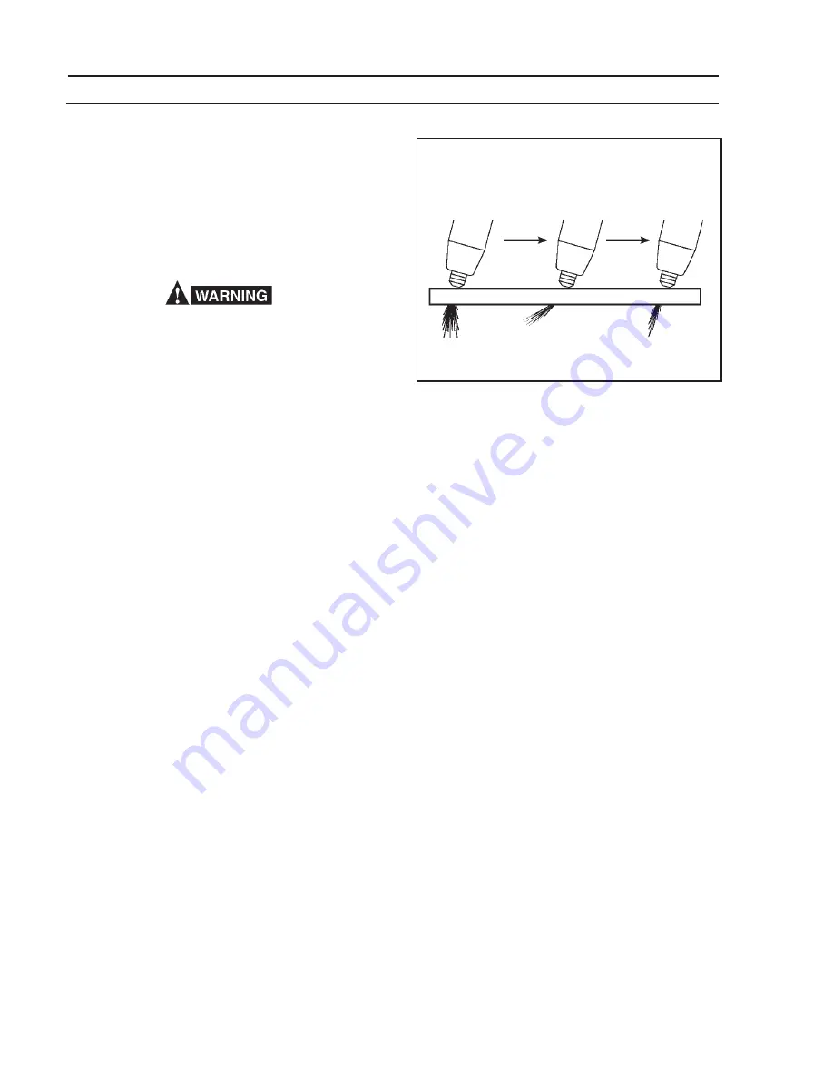
Fig. 4.1 - Effect of Cutting Speed

CORRECT

TOO FAST

TOO SLOW

Summary of Contents for HANDY PLASMA 125

Page 1: ...or Arc Welding Cutting and Gouging Form 52 529 Do NOT permit untrained persons to install operate or maintain this equipment Do NOT attempt to install or operate this equipment until you have read and...

Page 2: ...ation Section 4 Operation Section 5 Maintenance Section 6 PT 34 Torch Installation Operation and Maintenance Section 7 Replacement Parts Section 8 Electrical Diagrams Schematic Section 8 Electrical Di...

Page 3: ...s on the workpiece which might pro duce flammable or toxic vapors Do not do hot work on closed containers They may explode 4 Have fire extinguishing equipment handy for instant use such as a garden ho...

Page 4: ...Never strike an arc on a cylinder 5 For additional information refer to CGA Standard P 1 Precautions for Safe Handling of Compressed Gases in Cylinders which is available from Compressed Gas Associati...

Page 5: ...tie par des cha nes de PR CAUTIONS DE S CURIT AVERTISSEMENT Ces r gles de s curit ont pour objet d assurer votre protection Veillez lire et observer les pr cautions nonc es ci dessous avant de monter...

Page 6: ...es l alin a 6 de la norme Z49 1 de l AWS 5 ENTRETIEN DE L QUIPEMENT Un quipement entretenu de fa on d fectueuse ou inad quate ris que non seulement de r aliser un travail de mauvaise qualit mais chos...

Page 7: ...ION SECTION 2 EQUIPMENT PT 34 Torch Shipping Wgt 2 lbs 1 kg Length of Service Lines 15 3 8 m Dimensions Note the high open circuit voltage Use only plasma cutting torches designed for this equipment D...

Page 8: ...fan cooling Air is drawn in through the rear panel and then out the louvers in the front panel Locate the power supply in an open area where air can circulate freely through the open ings Allow at lea...

Page 9: ...in that order as shown in Figure 3 2 Electrode is reversible and the swirl baffle is symmetri cal They can be assembled either way Apply silicone grease to 0 ring See Figure 3 2 Tighten heat shield s...

Page 10: ...agged along the workpiece D OPERATING TECHNIQUES 1 Piercing Thin materials may be pierced with the torch touching the work When piercing thicker ma terials up to 1 8 in immediately raise the torch to...

Page 11: ...or Consumable Life a Improper gas pressure If this equipment does not operate properly stop work immediately and investigate the cause of the malfunction Maintenance work must be performed by an exper...

Page 12: ...cable for continuity Yes Power supply defective No High freq unit or compressor defective Depress torch switch Compressor and high freq should be seen or heard Does high freq come on with torch switch...

Page 13: ...g torch switch No Yes Check for short in torch switch Cuts normally when torch switch is depressed Yes Power supply defective No Defective control PCB Defective Thermal Switch No Is the fan running No...

Page 14: ...the nozzle tip to contact the electrode This contact would permit high voltage to be applied to the nozzle Your contact with the nozzle or workpiece could then result in serious injury or death by ele...

Page 15: ...line lay the line out straight remove the tape from around the switch lead splices and free the switch by cutting the leads close to the splices Re placement switches have extra long leads to make up...

Page 16: ...nal parts are included with spare parts kit No 37918 or may be purchased seperately ELECTRODE 37888 multiples of 2 SWIRL BAFFLE 18785 NOZZLE Tip 37887 multiples of 5 HEAT SHIELD 20282 SEAT 19679 Inclu...

Page 17: ...tighten fittings securely using 2 wrenches during reassembly Factory recommended torque is 30 in lbs Failure to do so could result in serious injury to the operator Pull flex support back Remove tape...

Page 18: ...ACITOR 800mf 450 VDC 37858 HOSE ASSEMBLY 0558001162 PRESSURE SWITCH 0558001159 PLUG HOUSING 15 POS 951504 PC BOARD LOGIC 38168 COOLING FAN 2046032 DIODE BRIDGE RECTIFIER 37855 GROMMET 212 ID 950518 GR...

Page 19: ...24 X 50 WASHER FLAT 10 DIODE BRIDGE RECTIFIER 37855 BULKHEAD ADAPTOR 58V75 NUT HEX 8 32 LOCKWASHER EXT TOOTH 8 COUPLING COIL HIGH FREQ 32969 ELBOW 1 4 NPT BUSHING SNAP 950823 SPARK GAP ASSEMBLY 055800...

Page 20: ...91514 HANDLE 951575 SCREW PHTF 10 24 X 38 LOGO ESAB 13734588 COVER 37952Y SCREW PHTF 10 24 X 38 LABEL DANGER HIGH VOLTAGE 954008 TORCH CABLE STRAIN RELIEF 0558001157 LOCKNUT 1 in CONDUIT 950435 TORCH...

Page 21: ...21 Figure 8 1 Handy Plasma 125 Schematic Diagram for 115V 60HZ Domestic and 230V Export Models NOTES 1 Connections for 115v Operation 2 Connections for 230V Operation D 0558001341 C...

Page 22: ...22 Figure 8 2a Handy Plasma 125 Wiring Diagram for 115V 60HZ Domestic and 230V Export Models D 0558001342 E...

Page 23: ...23 Figure 8 2b Handy Plasma 125 Wiring Diagram for 115V 60HZ Domestic and 230V Export Models D 0558001342 E...

Page 24: ...664 4452 Part Numbers Technical Applications Hours 8 00 AM to 5 00 PM EST Performance Features Technical Specifications Equipment Recommendations D LITERATURE REQUESTS Telephone 843 664 5562 Fax 843...

Reviews: