


ET 201i DC
0-5452
OPERATION
4-1
SECTION 4:
OPERATION
4.01 Instruction
Conventional operating procedures apply when using the Welding Power Source, i.e. connect work lead directly to work
piece and electrode lead is used to hold the electrode. The welding current range values should be used as a guide
only. Current delivered to the arc is dependent on the welding arc voltage, and as welding arc voltage varies between
different classes of electrode, welding current at any one setting would vary according to the type of electrode in use.
The operator should use the welding current range values as a guide then fine tune the welding current to suit the
specific application. Refer to the electrode manufacture's literature for further information.
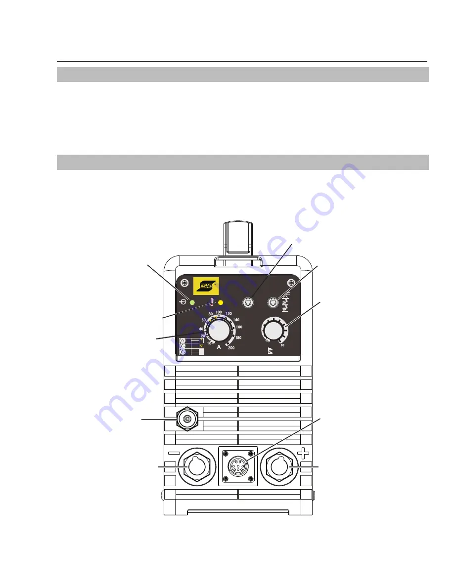
4.02 Front Panel
Front Panel
The welding power source is protected by a self re-setting thermostat. The indicator will illuminate if the duty cycle
of the power source has been exceeded. If the FAULT light illuminates wait for the FAULT light to extinguish before
resuming welding.
Art # A-13035
(A) Power On Indicator
(B) Fault Indicator
(E) Welding Current
Control
(G) Gas Outlet
Negative Output Terminal
Positive Output Terminal
(I) 8 Pin Control Socket
(F) Arc Force/Down
Slope Control
(D) Process Selection Switch
(C) Trigger Mode Selection Switch
32A OUTLET
STICK
TIG
230V
110V
TIG/STICK
32A OUTLET
16A OUTLET
4T
2T
8
2
4
6
0
(S)
(%)
SMAW
GTAW
15A
SMAW
20A
115V
50A
SMAW
GTAW
208/
230V
SMAW
GTAW
GTAW
PROCESS
TRIGGER
PROCESSUS
GÂCHETTE
Figure 4-1: ET 201i DC Controls


