ESAB EMP 285ic 1ph Instruction Manual Download Page 51

5 OPERATION

0463 618 001

- 51 -

© ESAB AB 2019

5.12.3

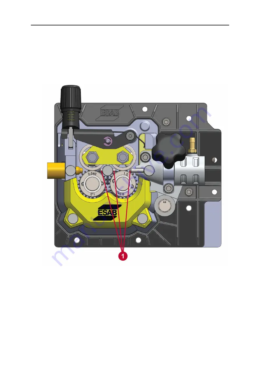
Adjusting wire guides

1.

Verify center wire-guide tube has clearance from each feed-roller. The center
wire-guide tube set screw should be finger-tight (see Figure 20 and 18). The center
wire-guide tube requires no adjustment, but it must be inserted completely to assure
clearance from the rollers.

2.

Adjust the output wire-guide tube for 1 mm (0.03 in.) of clearance from the right
feed-roller (see Figure 20), verify center wire-guide tube has clearance from each
feed-roller and tighten its thumb screw finger-tight.

Figure 20. Verify clearance of both guide tubes

1.

Roller and guide tubes

3.

Access the bitter-end of the wire on the bobbin and cut off the length from the bitter
end to have a clean, straight, bitter-end. This is needed to allow a
low-resistance-travel re-install of the wire along the length of the torch cable to the
torch tip.

4.

Feed the wire from the bobbin through the wire-feed guides laying the wire in the
grooves of the wire-feed rollers as shown in Figure 18. Lay the wire into the

inside

groove of the wire-feed rollers. Continue feeding the wire until it projects beyond the
torch-adapter output side by a few centimeters.

5.

Close the pressure rollers on the wire.

6.

Re-connect the torch assembly on the EMP unit.

Summary of Contents for EMP 285ic 1ph

Page 1: ...Instruction manual 0463 618 001 US 20190326 Valid for serial no 745 747 xxx xxxx EMP 285ic 1ph EMP 285ic 3ph ...

Page 2: ... 4 4 Mains supply 21 4 5 Recommended electrical supply specifications 22 4 6 Supply from power generators 22 5 OPERATION 23 5 1 Unit s connections and controls 24 5 2 Connection of welding and return cables 25 5 2 1 For MIG MMA process 25 5 2 2 For TIG process 25 5 3 Polarity change 26 5 4 Shielding gas 26 5 5 Volt ampere curves 26 5 5 1 1ph Volt ampere curves 26 5 5 1 1 SMAW Stick 120 V 1ph 26 5 ...

Page 3: ...ANEL 53 6 1 How to navigate 53 6 2 Main menu 53 6 3 sMIG mode Basic 53 6 4 sMIG mode Advanced 54 6 5 Manual MIG mode Basic 54 6 6 Manual MIG mode Advanced 54 6 7 Flux cored wire mode Basic 54 6 8 Flux cored wire mode Advanced 55 6 9 MMA mode Basic 55 6 10 MMA mode Advanced 55 6 11 Lift TIG mode Basic 56 6 12 Lift TIG mode Advanced 56 6 13 Settings 56 6 14 User manual information 56 6 15 Icon refer...

Page 4: ...E OF CONTENTS 0463 618 001 ESAB AB 2019 DIAGRAM 70 ORDERING NUMBERS 72 WEAR PARTS 73 ACCESSORIES 74 REPLACEMENT PARTS 75 ROLLER WIRE GUIDE SELECTION 76 Rights reserved to alter specifications without notice ...

Page 5: ...ury or death PROTECT YOURSELF AND OTHERS Some welding cutting and gouging processes are noisy and require hearing protection The arc like the sun emits ultraviolet UV and other radiation and can injure the skin and eyes Hot metal can cause burns Training in the proper use of the processes and equipment is essential to prevent accidents Therefore 1 Wear a welding helmet fitted with a proper shade o...

Page 6: ...s they may explode 5 Have fire extinguishing equipment handy for instant use such as a garden hose water pail sand bucket or portable fire extinguisher Be sure you are trained in its use 6 Do not use equipment beyond its ratings For example an overloaded welding cable can overheat and create a fire hazard 7 After completing work inspect the work area to make sure there are no hot sparks or hot met...

Page 7: ...alvanized steel stainless steel copper zinc lead beryllium or cadmium unless positive mechanical ventilation is provided Do not breathe in the fumes from these materials 3 Do not operate near degreasing and spraying operations The heat or arc can react with chlorinated hydrocarbon vapors to form phosgene a highly toxic gas and other irritant gases 4 If you develop momentary eye nose or throat irri...

Page 8: ...ice is finished and before starting engine WARNING FALLING EQUIPMENT CAN INJURE Do NOT use running gear gas cylinders or any other accessories Use equipment of adequate capacity to lift and support unit Keep cables and cords away from moving vehicles when working from an aerial location WARNING EQUIPMENT MAINTENANCE Faulty or improperly maintained equipment can cause injury or death Therefore 1 Al...

Page 9: ...l Personal Eye and Face Protection Devices 1 3 User responsibility Users of ESAB equipment have the ultimate responsibility for ensuring that anyone who works on or near the equipment observes all the relevant safety precautions Safety precautions must meet the requirements that apply to this type of equipment The following recommendations should be observed in addition to the standard regulations...

Page 10: ...ECTRIC AND MAGNETIC FIELDS Pose health risks Welders with pacemakers fitted should consult their doctor before welding EMF may interfere with some pacemakers Exposure to EMF may have other health effects which are unknown Welders should use the following procedures to minimize exposure to EMF Route the electrode and work cables together on the same side of your body Secure them with tape when poss...

Page 11: ...tion PROTECT YOURSELF AND OTHERS WARNING Do not use the power source for thawing frozen pipes CAUTION This product is solely intended for arc welding ESAB has an assortment of welding accessories and personal protection equipment for purchase For ordering information contact your local ESAB dealer or visit us on our website 1 4 California Proposition 65 Warning WARNING Welding or cutting equipment...

Page 12: ...stick electrode holder 12 ft 4 m 300 A Ground clamp 10 ft 3 m 300 A Victor Flow Meter with 6 ft 2 m gas hose ESAB OK AristoRod premium solid wire 0 035 in 0 9 mm 11 spool ESAB Atom Arc Acclaim 1 8 in premium stick electrodes 1 sample pack Drive rollers 0 035 in 0 9 mm to 0 045 in 1 2 mm V Groove 0 045 in 1 2 mm to 0 052 in 1 4 mm Knurled Guide tubes 0 030 in 0 8 mm to 0 062 in 1 6 mm Solid Wire Th...

Page 13: ...otection for its power supply The welding power source has overheating protection that operates if the internal temperature becomes too high When this occurs the welding current is interrupted and an overheating symbol appears on the display The overheating protection resets automatically when the temperature has returned to normal working temperature ...

Page 14: ... 5 V GTAW TIG 5 A Vout 10 2 V 285 A Vout 21 4 V 5 A Vout 10 2 V 200 A Vout 18 0 V SMAW Stick 16 A Vout 20 6 V t 180 A Vout 27 2 V 16 A Vout 20 6 V 130 A Vout 25 2 V Permissible load at GMAW MIG 100 duty cycle 160 A Vout 22 V Breaker 15 A 75 A Vout 17 75 V Breaker 20 A 90 A Vout 18 5 V 60 duty cycle 220 A Vout 25 V Breaker 15 A 90 A Vout 18 5 V Breaker 20 A 110 A Vout 19 5 V 40 duty cycle 285 A Vou...

Page 15: ...104 F 10 to 40 C Enclosure class IP23S Application class Duty cycle The duty cycle refers to the time as a percentage of a ten minute period that you can weld or cut at a certain load without overloading The duty cycle is valid for 104 F 40 C Enclosure class The IP code indicates the enclosure class i e the degree of protection against penetration by solid objects or water Equipment marked IP 23S ...

Page 16: ...out 18 8 V 60 duty cycle 265 A Vout 20 6 V 265 A Vout 20 6 V 50 duty cycle 285 A Vout 21 4 V 285 A Vout 21 4 V Permissible load at SMAW Stick 100 duty cycle 180 A Vout 27 2 V 180 A Vout 27 2 V 60 duty cycle 255 A Vout 30 2 V 255 A Vout 30 2 V 50 duty cycle 285 A Vout 31 4 V 285 A Vout 31 4 V Efficiency 87 87 Power factor 0 77 0 86 Open Circuit Voltage OCV 68 V 68 V Wire diameter Mild steel solid w...

Page 17: ...uty cycle is valid for 104 F 40 C Enclosure class The IP code indicates the enclosure class i e the degree of protection against penetration by solid objects or water Equipment marked IP 23S is intended for indoor and outdoor use however should not be operated in precipitation Application class The symbol indicates that the power source is designed for use in areas with increased electrical hazard...

Page 18: ...rmanent installation leave enough room to open door and access bobbin side 4 2 High frequency interference WARNING The high frequency section of this machine has an output like a radio transmitter The power source should NOT be used near blasting operations due to the danger of premature firing WARNING Operation close to computer installations may cause computer malfunction WARNING HIGH FREQUENCY ...

Page 19: ...invariably traced to improper installation A duly authorized person such as a properly licensed electrician should perform the installation to avoid injury death or any equipment damage 4 2 1 User s responsibility The user is responsible for installing and using the welding equipment according to the manufacturer s instructions If electromagnetic disturbances are detected then it shall be the resp...

Page 20: ...ower source will prevent direct radiation if the equipment is properly grounded Transmission via the supply lead Without adequate shielding and filtering high frequency energy may be fed to the wiring within the installation mains by direct coupling The energy is then transmitted by both radiation and conduction Adequate shielding and filtering is provided in the power source Radiation from weldin...

Page 21: ...r 120 V 10 For 3ph 460 V AC 10 or 575 V 10 Too low supply voltage may cause poor welding performance Too high supply voltage will cause components to overheat and possibly fail Contact the local electric utility for information about the type of electrical service available how proper connections should be made and inspection required The welding power source must be Correctly installed if necessa...

Page 22: ...m2 10 AWG Maximum recommended extension cord length 50 ft 15 m Minimum recommended grounding conductor size 5 3 mm2 10 AWG Recommended Electrical Supply Specifications 3 ph 50 60 Hz Specification Value Supply 10 460 V or 575 V Input current at maximum output 18 A Maximum recommended fuse or circuit breaker rating Time delay fuse 16 A Minimum recommended cord size 2 5 mm2 13 AWG Maximum recommended...

Page 23: ...start the equipment NOTE When moving the equipment use intended handle Never pull the cables WARNING Rotating parts can cause injury take great care WARNING Electric shock Do not touch the workpiece or the welding head during operation WARNING Assure that the side covers are closed during operation WARNING Tighten the bobbin bolt to prevent it from sliding off the hub ...

Page 24: ...current or wire feed speed selection 8 Positive output 2 Knob for voltage selection 9 Polarity changeover cable 3 Main knob for menu navigation 10 Display 4 Gas outlet 11 Gas inlet for MIG MAG 5 Torch remote control connection 12 Gas inlet for TIG 6 Torch connection 13 Main power switch ON OFF 7 Negative output 14 Main power cable ...

Page 25: ...rect electrode polarity Connect the return cable to the remaining welding terminal 9 on the power source Secure the return cable s contact clamp to the work piece and ensure that there is good electrical contact Connect the torch connector to the Torch connection 6 NOTE MIG welding guidance chart The backside of the door on the bobbin side displays a MIG welding guidance chart for initial selectio...

Page 26: ... by moving the polarity changeover cable to suit the applicable welding process 5 4 Shielding gas The choice of suitable shielding gas depends on the material Typically mild steel is welded with mixed gas Ar CO2 or 100 carbon dioxide CO2 Stainless steel can be welded with mixed gas Ar CO2 or trimix He Ar CO2 Aluminum and silicon bronze use pure argon gas Ar In the sMIG mode see sMIG mode section i...

Page 27: ...5 OPERATION 0463 618 001 27 ESAB AB 2019 5 5 1 2 SMAW Stick 230 V 1ph 5 5 1 3 GMAW MIG 120 V 1ph ...

Page 28: ...5 OPERATION 0463 618 001 28 ESAB AB 2019 5 5 1 4 GMAW MIG 230 V 1ph 5 5 1 5 GTAW TIG 120 V 1ph ...

Page 29: ...5 OPERATION 0463 618 001 29 ESAB AB 2019 5 5 1 6 GTAW TIG 230 V 1ph 5 5 2 3ph Volt ampere curve 5 5 2 1 SMAW Stick 460 V 3ph SMAW Stick 575 V 3ph ...

Page 30: ...3 GTAW TIG 460 V 3ph GTAW TIG 575 V 3ph 5 6 Duty cycle The duty cycle refers to the time as a percentage of a 10 minute period that you can weld or cut at a certain load without overloading If this occurs let the unit cool down for 10 minutes lower amperage voltage or duty cycle before welding ...

Page 31: ...uty cycle it will provide the rated amperage for a maximum of 4 minutes out of every 10 minute period The remaining time 6 minutes the power source must be allowed to cool down Figure 2 Example of 40 duty cycle A different combination of duty cycle and welding current can be selected Use the graphs below to determine the correct duty cycle for a given welding current ...

Page 32: ...5 OPERATION 0463 618 001 32 ESAB AB 2019 Figure 3 Example of 50 duty cycle Figure 4 Plotting duty cycle for 120 V 1ph AC ...

Page 33: ...g bobbin NOTE The gas need not be connected for this procedure Power should be turned off for this procedure The spring sets the braking value working against the wire feed motor and the pull of the roller feed wheels Tighten the bolt A see illustrations below hand tight Remove Install the bobbin as shown in below Tightening the bobbin locking nut for 100 mm 4 in ...

Page 34: ... come in the wire form shown in the illustration or may be molded plastic form Either mounts the same way as shown 5 8 Removing installing wire NOTE If installing aluminum wire see Welding with aluminum wire section The EMP 285ic will handle bobbin sizes of 100 mm 4 in 200 mm 8 in and 300 mm 12 in See TECHNICAL DATA chapter for suitable wire dimensions for each wire type ...

Page 35: ...bbin 3 Wire feed assembly 2 Gas valves WARNING Do not place or point the torch near the face hand or body as this may result in injury NOTE Make sure the correct wire feed rollers are selected NOTE Remember to use the correct contact tip in the welding torch for the wire diameter used ...

Page 36: ...001 36 ESAB AB 2019 5 8 1 Removing wire 1 Disconnect the electrical power source from the unit 2 Open the wire bobbin side cover of the EMP unit Figure 8 Wire bobbin side exposed view 1 Wire bobbin 2 Quad wire feed assembly ...

Page 37: ...ensioning arm 6 Input wire feed guide 3 Wire to torch 7 Wire in 4 Output wire feed guide 4 If wire remains in the torch assembly Near the input end of the wire feed guide on the wire feed assembly see Figure 9 cut the wire while holding the bobbin end so the wire does not unravel from the bobbin after cutting it loose Secure the cut end of the wire to the bobbin if any wire is left on the bobbin t...

Page 38: ...set the torch assembly aside with the loose wire still installed in the torch The old wire should now be completely removed from the wire feed assembly 7 Remove the bobbin from the unit see Removing installing bobbin section 8 If wire remains in the torch assembly Pull the length of old wire out of the torch assembly from either end of the torch assembly 5 8 2 Installing wire CAUTION Too long a to...

Page 39: ...bly to the EMP unit being careful to insert the bitter end of the wire protruding from the torch adapter into torch liner on the torch connector 9 Power up the EMP unit Gas does not need to be connected for this procedure 10 With the torch cable laid out reasonably straight feed the wire through the torch cable till visible at its welding tip by depressing the trigger switch on the torch Refer to ...

Page 40: ...or minimum roller pressure When you hold the welding torch approximately in 6 mm from the piece of wood see Figure 11 the wire feed rollers should slip If they don t reduce the tension on the wire by adjusting the tension knob on the wire feed assembly Figure 11 Check feed roller for slip indicating no over pressure 5 Adjusting for correct roller pressure If you hold the welding torch approximatel...

Page 41: ...election Figure 13 shows location of wire feed rollers The pressure rollers are not replaced Figure 13 Location of wire feed rollers and pressure rollers 1 Pressure rollers 2 Wire feed rollers 5 11 1 Removing wire feed rollers 1 If new rollers are being installed select the correct size and type steel or aluminum for wire being installed see Appendix C 2 Disconnect the electrical power source from...

Page 42: ...out of the way Figure 14 Wire feed mechanism 1 Tension knob 5 Center wire feed guide 2 Tensioning arm 6 Input wire feed guide 3 Wire to torch 7 Wire in 4 Output wire feed guide 5 Remove the wire from the wire feed mechanism CAUTION When removing the drive roller roller located on left side be careful not to remove the drive gear with it Doing so risks losing the small woodruff key on the motor sha...

Page 43: ...5 OPERATION 0463 618 001 43 ESAB AB 2019 Figure 15 Drive gear with woodruff key on motor shaft 1 Drive gear CAUTION Avoid removing drive gear see 1 in Figure 15 Risk loosing drive shaft woodruff key ...

Page 44: ...Installing wire feed rollers CAUTION When installing the wire feed rollers avoid and do not force installing a roller if either wire guide s position interferes Slide the offending wire guide slightly to provide clearance for the roller The wire guides are adjusted after the rollers are installed ...

Page 45: ...bels NOTE Label on roller side matches with the groove on the opposite side of the roller 2 Tighten the drive roller retaining screw by turning it in the clockwise direction Hand tight is sufficient 3 The wire must be installed through the wire feed assembly see Installing wire subsection NOTE If the wire was removed the wire will have to be re installed see Installing wire subsection 4 Close the ...

Page 46: ...ube center wire guide tube and output wire guide tube The input wire guide tube and the center wire guide tube are standard parts for all wire types sizes so they are not mentioned here This procedure addresses the removal installation and then adjustment of the output wire guide tube NOTE This section requires that the wire feed rollers have been removed to provide access to the wire guides Perfo...

Page 47: ...ure 18 Location of wire guides and their set screws 1 Wire from bobbin 5 Wire path through assembly 2 Input wire guide 6 Output wire guide thumb screw 3 Center wire guide 7 Center wire guide set screw 4 Output wire guide tube 8 Wire feed rollers ...

Page 48: ...e steel or aluminum wire selected it is assumed that the wire is already selected obtained and available for this procedure 1 Center wire guide one size fits all 2 Output wire guide 4 sizes for steel 3 sizes for aluminum select from table in Appendix C 2 Disconnect the electrical power source from the unit 3 Open the cover on the wire bobbin side of the EMP unit ...

Page 49: ... convenient means to the wire frame of the bobbin to mechanically restrain it while this procedure continues 6 Disconnect the torch assembly from the EMP unit by loosening the torch connector holding knob and disconnecting the torch connector 7 Pull the remaining length of the wire through the wire feed assembly and with the torch set the torch assembly aside with the loose wire still installed in...

Page 50: ... size tube in the reverse order Do not tighten its set screw now will be done below in Adjustment 5 12 2 Center wire guide removal installation 1 Loosen and remove the original center wire guide tube see Figure 18 for location This center wire guide tube removes installs only from the left side 2 Install the new center wire guide tube Slide this tube narrow part first and from the left side into i...

Page 51: ...b screw finger tight Figure 20 Verify clearance of both guide tubes 1 Roller and guide tubes 3 Access the bitter end of the wire on the bobbin and cut off the length from the bitter end to have a clean straight bitter end This is needed to allow a low resistance travel re install of the wire along the length of the torch cable to the torch tip 4 Feed the wire from the bobbin through the wire feed ...

Page 52: ...isible at its welding tip by depressing the trigger switch on the torch Refer to the relevant Torch manual for length of wire protrusion at tip end 9 Adjust the wire feed pressure by adjusting the tension on the wire at the wire feed rollers by using the procedure in Setting the wire feed pressure section for a more accurate adjustment of this tension knob 10 Close the cover on the wire bobbin sid...

Page 53: ...er power on has completed the main menu appears on the control panel 6 1 How to navigate 1 Upper control knob a Set current output value b Set wire feed speed 2 Lower control knob a MIG Voltage Selection b sMIG Voltage Trim c MMA Mode ARC ON OFF 3 Menu navigation Push to select 6 2 Main menu 1 sMIG mode 2 Manual MIG mode 3 Flux cored wire mode 4 MMA mode 5 Lift TIG mode 6 Settings 7 User manual 8 ...

Page 54: ...ox 6 5 Manual MIG mode Basic 1 Home screen 2 Information 3 Memory 4 Material selection 5 Parameter 6 Wire feed speed 7 Voltage adjustment 8 Dialogue box 6 6 Manual MIG mode Advanced 1 Home screen 2 Information 3 Memory 4 Material selection 5 Parameter 6 Wire feed speed 7 Voltage adjustment 8 Dialogue box 6 7 Flux cored wire mode Basic 1 Home screen 2 Information 3 Memory 4 Wire feed speed 5 Voltag...

Page 55: ...ic 1 Home screen 2 Information 3 Memory 4 Amperage adjustment 5 Power supply output voltage Open Circuit Voltage or Arc 6 Dialogue box 7 Arc ON OFF Blue changes to orange when output is hot 6 10 MMA mode Advanced 1 Home screen 2 Information 3 Memory 4 Parameter 5 Amperage 6 Power supply output voltage Open Circuit Voltage or Arc 7 Arc ON OFF 8 Dialogue box Blue changes to orange when output is hot...

Page 56: ... Lift TIG mode Advanced 1 Home screen 2 Information 3 Memory 4 Parameter 5 Amperage 6 Dialogue box 6 13 Settings 1 Reset modes 2 Inch Metric 3 Basic Advanced 4 Language 5 Information 6 Home screen 7 Dialogue box 6 14 User manual information 1 Maintenance information 2 Wear Spare parts 3 Operation information 4 Home screen 5 Dialogue box ...

Page 57: ...spray and flux core welding traditional burn back is recommended When burn back time is set to zero SCT automatically is enabled A non zero burn back setting will disable SCT ICON MEANING ICON MEANING Home Spot time on off selection use navigation knob and push to select from display Burn back Adjusting the time when the voltage stays on after the wire feed is stopped to keep the wire from freezin...

Page 58: ... for a specific application when in the Memory Mode Settings on user manual menu Cancel Spool torch Not all markets Remote Settings Foot control 2T Trigger On OFF Volts 4T Trigger Hold Lock User manual on main menu Amps Plate thickness at sMIG mode Arc force On stick welding increasing amps when the arc length is shortened to reduce or eliminate the freezing of the stick electrode in the weld pudd...

Page 59: ...reduce sticking Basic Settings Inductance The addition of inductance into the arc characteristics to stabilize the arc and reduce spatter when in the short circuit process Language selection Memory Ability to save welding programs for a specific application Stick electrode choice Upslope Sloping the current up over a period of time at the beginning of the weld cycle Unit of Measure Wire diameter B...

Page 60: ...ot damaged The nozzle on the torch is clean and does not contain any debris NOTE Perform maintenance more often during severe dusty conditions NOTE There are no user serviceable parts inside of the power supply side of the EMP unit Any need for service on the electronics electrical power side should be referred to the nearest ESAB service center 7 1 Routine maintenance Maintenance schedule during ...

Page 61: ...wing three illustrations for reference during this procedure 1 Wire from bobbin 6 Output wire guide inside of Euro adapter assy 2 Input wire guide 7 Wire path through assembly 3 Center wire guide 8 Output wire guide thumb 4 Output wire guide tube 9 Center wire guide set screw 5 Eurro adapter assembly 10 Wire feed rollers Wire feed assembly parts location ...

Page 62: ...7 MAINTENANCE 0463 618 001 62 ESAB AB 2019 1 Pressure rollers 2 Wire feed rollers Wire feed pressure roller locations ...

Page 63: ...sh or use a forced air source by blowing compressed air max 5 bar to remove all debris which may have accumulated in this space WEAR EYE PROTECTION 5 Inspect if the input wire feed guide the output wire feed guide the center wire feed guide or the feed rollers are worn and need replacement See WEAR PARTS section for ordering wear part numbers See Removing wire feed rollers subsection in Removing I...

Page 64: ...ally verify that the wire protrudes per specification at the torch tip and has not been pulled into the torch head 14 Adjust the wire feed pressure by adjusting the tension on the wire at the wire feed rollers by turning the tension knob using the procedure in Setting wire feed pressure subsection in OPERATION chapter 15 Close the door on the wire bobbin side of the EMP unit 7 3 EMP unit power sid...

Page 65: ...r damage or kinks Clean the liner by blowing compressed air max 5 bar through the end of the liner that was mounted closest to the unit 5 Re install the liner 6 Re install the wire through the wire feed assembly until visible at the torch tip Verify that the wire does correctly feed out of the torch ...

Page 66: ... areas where drafts which would disburse the shielding gas are common Make sure the work piece is clean with no oil or grease on the surface before welding Wire feeding problems Make sure the wire spool brake is adjusted correctly Make sure the feed roller is correct size and not worn Make sure the correct pressure is set on the feed rollers Make sure the proper direction of motion is set based on...

Page 67: ...d Check that the correct current value is set Check the input power supply fuses breakers The overheating protection trips frequently Make sure that you are not exceeding the recommended duty cycle for the weld current you are using See the Duty cycle section in the OPERATION chapter Make sure the air inlets or outlets are not clogged Make sure fans are operating when welding 8 2 User interface UI...

Page 68: ...factory reset and this was not confirmed by the system 012 C Communication Link Down no communication between UI and Ctrl PCB at CN6 013 C Low Internal Power Supply IPS Voltage Error 24 V IPS is less than 22 V DC 014 C Secondary Current Sensor output not detected at Control PCB CN18 015 019 reserved 020 C No Image found in Flash 021 C The image read from the flash is corrupted 022 NC Failed two at...

Page 69: ...5ic 3ph is designed and tested in accordance with international standards IEC EN 60974 1 IEC EN 60974 5 IEC EN 60974 7 IEC EN 60974 10 IEC EN 60974 12 and IEC EN 60974 13 It is the obligation of the authorized service centre carrying out the service or repair work to ensure that the product still conforms to the aforementioned standards The spare parts list is published in a separate document that...

Page 70: ...h 9 Output Inductor 2 EMI Filter Board 10 Internal Power Supply Power Board 3 Primary Rectifier on Power Board 11 Control Board 4 Primary Inverter on Power Board 12 User Interface UI 5 Main Transformer 13 Wire Feeder 6 Ferrite Cores 14 Gas Valves 7 Output Diode Assembly 15 Fans 8 Current Sensor ...

Page 71: ...l breaker 9 Output Inductor 2 Primary Rectifier on Power Board 10 Internal Power Supply on Power Board 3 Boost PFC 11 Control Board 4 Primary Inverter on Power Board 12 User Interface UI 5 Main Transformer 13 Wire Feeder 6 Ferrite Rings 14 Gas Valves 7 Output Diode Assembly 15 Fans 8 Current Sensor ...

Page 72: ...001 72 ESAB AB 2019 ORDERING NUMBERS Ordering no Description Note 0558 102 554 EMP 285ic 1ph Bobbin Size 4 12 in 100 300 mm bayonet 0558 102 556 EMP 285ic 3ph Bobbin Size 4 12 in 100 300 mm bayonet 0463 619 001 Spare Parts List ...

Page 73: ... Roller wire guide selection section in Appendix OUTPUT WIRE GUIDE TUBE 1 5 0558 102 609 MOTOR GEAR SHAFT WOODRUFF KEY 1 6 0558 102 597 INLET QUAD WF 1 7 0558 102 605 DRIVEN GEAR ASSEMBLY 2 8 0558 102 606 DRIVE GEAR ASSEMBLY 1 9 See Roller wire guide selection section in Appendix WIRE FEED ROLLERS 2 10 0558 102 600 WASHER FLAT M4 LARGE OD 3 11 0558 102 601 THUMB SCREW M4 X 10 X 8 KNURLED 2 12 0558...

Page 74: ...V 15 ft 4 5 m 0558 102 493 TIG torch TXH 201 12 ft 4 m TIG torch c w 8 pin plug W4 014 450 Foot control Contactor on off and current control with 14 74 ft 4 5 m cable and 8 pin male plug 0558 102 491 Rebel single cylinder cart Accommodates 1 9 in 228 6 mm diameter cylinder 0558 102 492 Rebel dual cylinder cart Accommodates 2 9 in 228 6 mm diameter cylinders ...

Page 75: ...escription 1 0781 2743 Victor Flow Meter with 10 ft 3 m gas hose 2 WS200G10 Tweco Ground Clamp w Lead 10 ft 3 m 50 mm Dinse 3 WS200E13 Electrode Holder 200A and Lead Assembly 13 ft 4 m 50 mm Dinse 4 W4014000 Power adapter cable 230 V to 120 V 15 A 5 354TA8 Adapter cable 4 pin to 8 pin ...

Page 76: ...AULT size included in package ACCESSORY optional size included with each model Wire Guide Selection Item Ordering no Description Comment Output wire guide tubes except for aluminum wire 1 0558 102 585 TUBE WIRE GUIDE 024 6 V SOLID OPTIONAL FOR PURCHASE 2 0558 102 584 TUBE WIRE GUIDE 030 8 040 1 0 V SOLID ACCESSORY 3 0558 102 582 TUBE WIRE GUIDE 035 0 9 045 1 2 V SOLID DEFAULT 4 0558 102 583 TUBE W...

Page 77: ...ROLLER WIRE GUIDE SELECTION 0463 618 001 77 ESAB AB 2019 ...

Page 78: ...For contact information visit esab com ESAB AB Lindholmsallén 9 Box 8004 402 77 Gothenburg Sweden Phone 46 0 31 50 90 00 http manuals esab com ...

Reviews: