INSTALLATION AND CONNECTIONS
0740 801 028
- 19 -
© ESAB AB 2017
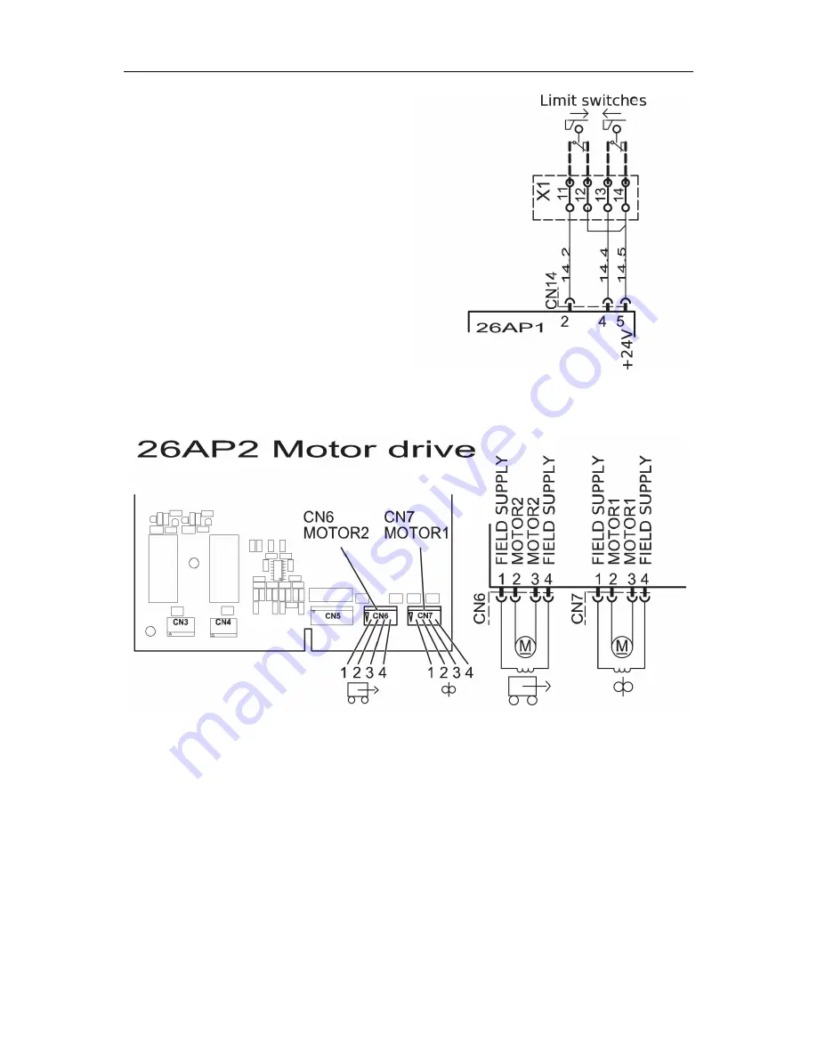
Travel limit switches
There are two inputs for limit switches.
• At terminal block X1, remove link
between 11 and 12.
• At terminal block X1, remove link
between 13 and 14.
• Connect the first limit switch to terminal
block X1 at 11 and 12.
• Connect the second limit switch to
terminal block X1 at 13 and 14.
Connection for limit switches
Motor drive and field supply
Power connection to motor 1 and 2
There are outputs to drive two motors. The motors are connected directly to the 26AP2 motor
drive board with an ESAB accessory cable.
Motor 1 for wire feed, connect to CN7.
Motor 2 for travel, connect to CN6.
•
At the back of the unit, remove the plug(s) from the hole(s).
•
Push the board connector(s) through the hole(s) and secure the strain relief(s).
•
Connect to the motordrive board 26AP1 at CN6 and/or CN7.
Summary of Contents for A2-A6 PEK
Page 9: ...WIRING DIAGRAM 0740 801 028 9 ESAB AB 2017...
Page 10: ...WIRING DIAGRAM 0740 801 028 10 ESAB AB 2017 A2 A6 PEK Control Unit Serial no 628 xxx xxxx...
Page 11: ...WIRING DIAGRAM 0740 801 028 11 ESAB AB 2017...
Page 39: ...DESCRIPTION OF OPERATION 0740 801 028 39 ESAB AB 2017 26AP1 Component positions...
Page 41: ...DESCRIPTION OF OPERATION 0740 801 028 41 ESAB AB 2017 26AP2 2 Motor 1 drive Wire feed at CN7...
Page 46: ...DESCRIPTION OF OPERATION 0740 801 028 46 ESAB AB 2017 26AP2 Component positions...


