background image


1.4 

Connectors 

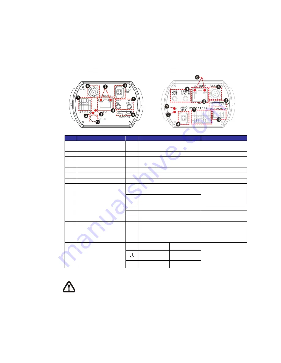
The diagram below shows the various connectors of the camera. Definition for 

each connector is given as follows. 


DC 12V / PoE


DC 12V / AC 24V / PoE 


No.


Item


Pin 

Definition


Remarks 

Audio I/O 
(Line In/Out) 

Two-way audio transmission


Power LED 

For power connection indication (green light)


Default Button


Press the button with a proper tool for at least 20 
seconds to restore the system. 

Auto Iris


For auto iris lens connection 

RJ-45


For network and PoE connections 

Network LEDs


For network connection and activity indication 

Alarm I/O *


Alarm Out + 

Alarm connection 

Alarm Out – 

Alarm In + 

Alarm In – 

5


GND


Ground connection 

6


– 

RS-485 connection 

7


D +


BNC


For analogue video output 

microSD Card Slot


Insert the microSD card into the card slot to store 
videos and snapshots. Do not remove the microSD 
card when the camera is powered on. 

10 

Power   
(DC12V / AC 24V) 
(AC 24V Model) 


DC 12V 

AC 24V 1 

Power connection 


DC 12V 
Reserved 

AC 24V GND 


DC 12V GND    AC 24V 2 

*Do 

NOT

 connect external power supply to the alarm I/O connector of the camera.


NOTE:

 It is not recommended to record with the microSD card for 24/7 

continuously, as it may not be able to support long term continuous data 

read/write. Please contact the manufacturer of the microSD card for 

information regarding the reliability and the life expectancy. 


Summary of Contents for TAURUS DX 2 SERIES

Page 1: ...TAURUS DX 2 SERIES Low Light Box Camera User s Manual Ver 2 0...

Page 2: ...Lens Mounting 7 2 4 Alarm I O Connection 7 2 5 RS 485 Connection DC12V AC24V PoE Models 7 3 System Requirements 8 4 Access Camera 9 4 1 Lock ABF Function ABF Models Only 13 5 Setup Video Resolution 1...

Page 3: ...D Multi Streams Ultra WDR Box IP Camera is built in with Auto Back Focus ABF function User can simply adjust focus by clicking control buttons on webpage that makes focus adjustment easier and also ma...

Page 4: ...ackage containing the following items listed below Full HD Multi Streams Ultra WDR Box IP Camera Back Focus Adjuster Quick Guide For Non ABF models NOTE To purchase power adaptor please contact the ca...

Page 5: ...4 1 3 Dimensions The IP camera s dimensions are shown below Non ABF Models ABF Models...

Page 6: ...rm Out Alarm connection 2 Alarm Out 3 Alarm In 4 Alarm In 5 GND Ground connection 6 D RS 485 connection 7 D 8 BNC For analogue video output 9 microSD Card Slot Insert the microSD card into the card sl...

Page 7: ...y users can power up the camera by PoE if a Power Sourcing Equipment PSE switch is available Refer to the section below for Ethernet cable connection NOTE If PoE is used make sure PSE is in use in the...

Page 8: ...rotective film from the CMOS image sensor Step 3 For Non ABF models mount the C CS Mount Adapter to the camera Step 4 Attach the C CS Mount Lens to the adapter C CS Mount Adapter Completion 2 4 Alarm...

Page 9: ...ded 1 Intel CoreTM i7 870 2 93 GHz 2 8 GB RAM Operating System Windows VISTA Windows XP Windows 7 Web Browser Microsoft Internet Explorer 7 0 or later recommended Firefox 32 bit Safari Network Card 10...

Page 10: ...IP address of the camera may not be in the same LAN as the IP address of the PC If so the IP address of the camera needs to be changed Right click on the camera and click Network Setup Meanwhile reco...

Page 11: ...eb browser doesn t allow DCViewer installation please check the Internet security settings or ActiveX controls and plug ins settings refer to section Setup Internet Security to continue the process Th...

Page 12: ...11 Once the Viewer is successfully installed the Home page of the camera will be displayed as the figure below Non ABF Models...

Page 13: ...12 ABF Models NOTE For more details about the function buttons on the Home page please refer to the Full HD Multi Streams Ultra WDR IP Camera Menu Tree...

Page 14: ...afterwards or is accidentally adjusted locally or remotely via NVR VMS Step 1 Once the camera is powered on click on Step 2 Manually adjust the lens to the approximate zoom and focus position Step 3 C...

Page 15: ...iguration interface Video Format can be found under this path Streaming Video Format The default values of video resolution are as below 1 3M H 264 1280 x 720 25 30 fps H 264 1280 x 720 25 30 fps 2M H...

Page 16: ...ing configuration file to the camera It is especially convenient to make multiple cameras having the same configuration Export Users can save the system settings by exporting the configuration file bi...

Page 17: ...IP camera Deleting the DCViewer In the Windows Start Menu activate Control Panel and then double click on Add or Remove Programs In the Currently installed programs list select DCViewer and click on...

Page 18: ...der ActiveX controls and plug ins set ALL items as listed below to Enable or Prompt Please note that the items vary by IE version ActiveX controls and plug ins settings 1 Binary and script behaviors 2...

Page 19: ...How to adjust back focus Step 1 Set the camera on a stable mount and place the test chart or the contrasting object at a far location at least 10 meters Step 2 Adjust the focus to infinite far positio...

Reviews: