background image


1.4 

Connectors 

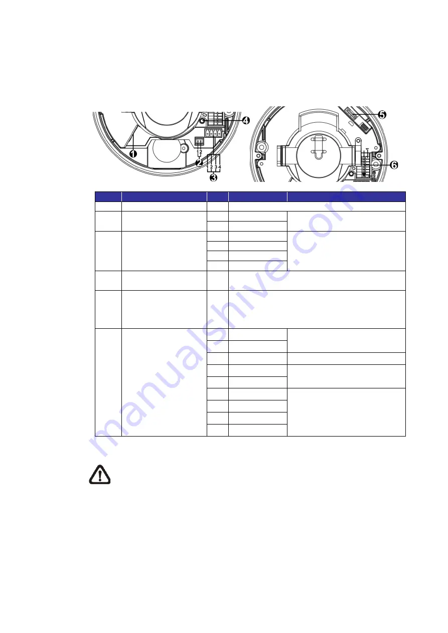
The diagram below shows the default  button and various connectors  of the 
camera. Definition for each connector is given as follows. 


No. 

Connector 

Pin 

Definition 

Remarks 

RJ-45 

-  For network and PoE connections 

BNC* 

1  GND 

For analog video output 

2  BNC 

Power 

(DC 12V / AC 24V) 

1  AC 24V 1 

Power connection 

2  AC 24V 2 

3  DC 12V 1   

4  DC 12V 2 

Default Button 

-  Press the default button with a proper tool for 

at least 20 seconds to restore the camera. 

microSD Card Slot 

Insert the microSD card into the card slot to 

store videos and snapshots.    Do not remove 

the microSD card when the camera is powered 

on. 

Alarm & Audio I/O 

1  Audio In L 

Audio In (Line In) 

2  Audio In R 
3  GND 

Ground connection 

4  Audio Out L 

Audio Out (Line Out) 

5  Audio Out R 
6  Alarm Out + 

Alarm connection 


**Do 

NOT

  connect external 

power supply to the alarm I/O 

connector of the IP camera.   

7  Alarm Out 


8  Alarm In + 
9  Alarm In 


*Please contact the manufacturer for the compatible BNC cable. 


NOTE:

 It is not recommended to record with the microSD card for 24/7 

continuously, as it may not be able to support long term continuous data 
read/write. Please contact the manufacturer of the microSD card for 
information regarding the reliability and life expectancy. 


Summary of Contents for MERCURY SX 5TH GENERATION

Page 1: ...2018SX5MA_v1 MERCURY SX 5TH GENERATION IR Dome IP Camera User s Manual Ver 1 1...

Page 2: ...abling 6 2 1 Connect Power 6 2 2 Connect Ethernet Cable 6 2 3 Connect Alarm I O 7 2 4 Camera Installation 7 3 System Requirements 9 4 Access Camera 10 5 Setup Video Resolution 14 6 Configuration Files...

Page 3: ...ighting condition The camera operating temperature ranges from 55 C to 55 C 1 1 Features Multiple Progressive Scan CMOS Sensor Support up to 4MP Resolution Multi Exposure HDR Multi Codec Support H 265...

Page 4: ...er supply please contact the camera manufacturer to confirm that the power supply uses the same power specifications as the camera The power supply must comply with the LPS requirements NOTE Users MUS...

Page 5: ...4 1 3 Dimensions The dimensions of the camera are shown below...

Page 6: ...he card slot to store videos and snapshots Do not remove the microSD card when the camera is powered on 6 Alarm Audio I O 1 Audio In L Audio In Line In 2 Audio In R 3 GND Ground connection 4 Audio Out...

Page 7: ...to the section below for Ethernet cable connection NOTE If PoE is used make sure PSE is in use in the network 2 2 Connect Ethernet Cable To have best transmission quality cable length shall not excee...

Page 8: ...to the ceiling or to the wall NOTE This camera must be installed by qualified personnel and the installation should conform to all local codes Step 1 Loosen the two security screws on the camera with...

Page 9: ...ed screw hole Then insert the plastic screw anchors into the drilled holes Step 6 Thread the cables through the cable entry hole Match the two screw holes on the camera with the plastic screw anchors...

Page 10: ...2 4 GB RAM Recommended 1 Intel CoreTM i7 870 2 93 GHz 2 8 GB RAM Operating System Windows VISTA Windows XP Windows 7 Windows 10 Web Browser Microsoft Internet Explorer 11 0 recommended Chrome Firefox...

Page 11: ...t IP address of the camera may not be in the same LAN as the IP address of the PC If so the IP address of the camera needs to be changed Right click on the camera and click Network Setup Meanwhile rec...

Page 12: ...doesn t allow DCViewer installation please check the Internet security settings or ActiveX controls and plug ins settings refer to section Setup Internet Security to continue the process The Informati...

Page 13: ...12 Once the Viewer is successfully installed the Home page of the IP camera will be shown as the figure below Zoom Lens Models...

Page 14: ...be displayed on the Home page when the camera is successfully accessed If zoom or focus is not at the desired position please use the function buttons on the Home page for adjustment Refer to the H 2...

Page 15: ...configuration interface Video Format can be found under Streaming Video Configuration The default values of video resolution are as below 4M H 265 H 264 2688 x 1512 30 25 fps H 265 H 264 800 x 600 30...

Page 16: ...g configuration file to the camera This is especially convenient to make multiple cameras having the same configuration Export Users can save the system settings by exporting the configuration file bi...

Page 17: ...then double click on Add or Remove Programs In the Currently installed programs list select DCViewer and click on the button Remove to uninstall the existing DCViewer Deleting Temporary Internet Files...

Page 18: ...Under ActiveX controls and plug ins set ALL items as listed below to Enable or Prompt Please note that the items vary by IE version ActiveX controls and plug ins settings 1 Binary and script behaviors...

Reviews: