background image

LBI-38836

12

messages may only be issued on
EDACS systems.

SPC

Pressing the SPC call key will put
the radio in the Special Call Mode.
From the Special Call Mode the
radio is able to make individual and
interconnect calls. This key is active
with trunked systems only.

SCAN-A/D

The SCAN-Add/Delete key is used
to enable the Scan mode and toadd
or delete Groups/Channel to the
Scan list.

STO

The STOre key in combination with
the SHIFT/CLR button is used to
store Individual Call numbers and
Interconnect numbers. This is
available on System Model radios
and is active with trunked systems
only.

LOCK

The LOCK key in combination with
the SHIFT/CLR key is used to lock
the keypad. All buttons and keys
will be locked except the VOLUME,
PTT, HOME/E, SHIFT/CLR and
the LOCK (shifted 0). This key is
available on System models only.

RCL

The RECALL key (shifted #) can be
used to recall manually entered
individual and interconnect calls in
the EDACS and GE-MARC
systems. This is available on System
model radios and is active with
trunked systems only.

INDICATORS

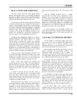
Figure 3 - Dual Format PCS Display

The 4-digit LIQUID CRYSTAL DISPLAY (LCD) uses

the two digits on the left side to indicate the System number
and the two digits on the right side to indicate the

Group/Channel number. In addition there are 9 status
indicators.

LCD backlighting can be programmed to turn on

anytime a button or key is pressed. It will remain on for a
programmable length of time after the button or key is
released. Backlighting is programmed on a per Group/
Channel basis or it may be programmed to remain off at all
times. Each radio that is programmed with backlighting may
also be programmed to remain on or off when the PTT bar is
pressed.

System And Group/Channel Indicators

The SYStem display indicates the
number of the current EDACS, GE-
MARC or Conventional system
selected.

The GRP (Group) display indicates
the number of the current Group in
an EDACS or GE-MARC System.
The GRP icon is suppressed while
operating from a Conventional
System, but the field is still used to
display the Channel selected.

Status Indicators

TX

The Transmitter flag is on when the
radio is transmitting.

BSY

The Channel Busy flag is on when
the radio receives a call or when a
conventional channel is in use. The
flag is also on when transmitting on
a trunked channel. This flag flashes
when a call is qued on a trunked
system.

BT

The Battery flag is on when the
battery power is low and needs
charging.

NO

EDACS - The NO Service flag is
used in conjunction with the Service
flag to indicate no service. The
illumination of both the NO and the
SV flag indicates a no service
condition.

GE-MARC - The NO flag is used in
conjunction with the Service flag to
indicate an unsuccessful attempt to

Summary of Contents for LBI-38836A

Page 1: ...LBI 38836A ericssonz Maintenance Manual DUAL FORMAT PCS 800 MHz PORTABLE RADIO COMBINATION TABLE OF CONTENTS FRONT ASSEMBLY LBI 38855 REAR ASSEMBLY LBI 38856 SERVICE SECTION LBI 38857...

Page 2: ...warranty This manual is published by Ericsson Inc without any warranty Improvements and changes to this manual necessitated by typographical errors inaccuracies of current information or improvements...

Page 3: ...BATTERY PACK 14 CHARGING THE BATTERY PACKS 14 CHANNEL GUARD ENCODE DECODE 15 EDACS SYSTEM DESCRIPTION 17 GE MARC SYSTEM DESCRIPTION 17 ORIGINATING A CALL 18 OPERATIONAL MODES 18 READY MODE Figure 10 O...

Page 4: ...tion EIA USFS MIL STD 810E METHOD 514 4 PROCEDURE 1 Shock EIA MIL STD 810E METHOD 516 4 PROCEDURE 1 4 Relative Humidity EIA MIL STD 810E METHOD 507 3 PROCEDURE 2 Altitude 15000 Feet Construction Front...

Page 5: ...B 30 dBm Radiated Spurious 65 dB 30 dBm Deviation 5 kHz 4 kHz NPSPAC Audio Response EIA Hum And Noise 40 dB Audio Distortion 5 max RECEIVER Frequency Range 851 870 MHz Audio Output 5 Watt Sensitivity...

Page 6: ...Top Long Battery FM Approved PCHC5V Case With Strap Long Battery FM Approved PCNC3L Antenna Whip 806 870 MHz PCPA1J High Capacity Battery Pack PCPA1K Extra High Capacity Battery Pack PCPA1L Extra Hig...

Page 7: ...S GROUPS SYSTEM EGE PC8TGS 800 MHz DUAL FORMAT 625 SYS GROUPS SCAN EGE PC8TGD 800 MHz DUAL FORMAT 625 SYS GROUPS SYSTEM EGE PC8LES 800 MHz DUAL FORMAT 9 SYS GROUPS SCAN ERICSSON PC8LED 800 MHz DUAL FO...

Page 8: ...all logic and control circuits The Control Frame assembly mounts in the radio front cover and provides the following functions Audio Logic board interface Microphone and speaker connections Houses the...

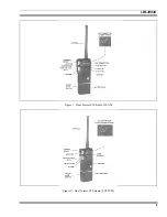
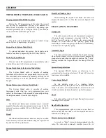
Page 9: ...LBI 38836 9 Figure 1 Dual Format PCS Radio SCAN Figure 2 Dual Format PCS Radio SYSTEM...

Page 10: ...recalled from a memory location and initiated using the Special Call key and the RCL key shifted Recall Last Number Send When entering the Special Call Mode the radio will display the number 0 9 of th...

Page 11: ...pack The radio will beep once after power is applied indicating it is ready for use PTT BUTTON Push To Talk Pressing the PTT Button on the side of the radio will key the radio s transmitter and perfor...

Page 12: ...addition there are 9 status indicators LCD backlighting can be programmed to turn on anytime a button or key is pressed It will remain on for a programmable length of time after the button or key is...

Page 13: ...The 1 flag is used only for radio logical ID display When receiving an individual call the most significant digit 0 or 1 of the originating radio s ID will be displayed by the 1 flag When on the ID o...

Page 14: ...uce the life of the battery between charges The most common method of producing this limited capacity is regularly performing short duty cycles when the battery is operated so that only a portion 2 of...

Page 15: ...ents are shown in Table 2 Table 1 CG Tone Frequencies Standard Tone Frequencies Hz 67 0 97 4 136 5 192 8 71 9 100 0 141 3 203 5 74 4 103 5 146 2 210 7 77 0 107 2 151 4 79 7 110 9 156 7 82 5 114 8 162...

Page 16: ...03 074 360 721 365 107 036 137 114 327 615 371 217 453 350 053 115 534 674 411 117 756 122 535 116 060 737 412 127 441 711 145 525 125 173 413 133 620 212 253 131 572 702 423 234 563 621 713 225 536 1...

Page 17: ...nd will give a channel assignment to the requesting portable as soon as a voice channel is free If the system is busy and the station queue is filled to capacity a system busy message will be sent bac...

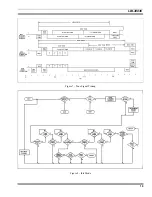
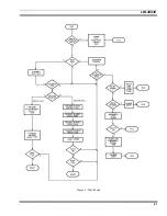
Page 18: ...low Charts for each operational mode are shown in Figures 8 9 and 10 Idle Mode Figure 8 When the radio is in the Idle Mode the audio is muted and all channels programmed for call decode are sequential...

Page 19: ...LBI 38836 19 Figure 7 Tone Signal Timing Figure 8 Idle Mode...

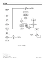
Page 20: ...n acquired the portable enters the Ready mode In this mode the audio and push to talk circuits are enabled the speaker is unmuted and the operator is alerted an alert tone The radio can then be used i...

Page 21: ...LBI 38836 21 Figure 9 Wait Mode...

Page 22: ...LBI 38836 Ericsson Inc Private Radio Systems Mountain View Road Lynchburg Virginia 24502 1 800 528 7711 Outside USA 804 528 7711 Printed in U S A Figure 10 Ready Mode...

Reviews: