background image

       ROUTER

Declaration of Conformity

We, Importer

Screwfix Direct Ltd

Mead Avenue

Houndstone Business Park

Yeovil

BA 22 8RT

Declare that the product

1/2” Router 

ERB210C

Complies with the essential health and safety requirements of the following directives:

89/336 EEC, 93/68 EEC 

– EMC Directive.

73/23 EEC, 93/68 EEC 

– Low Voltage Directive

98/37 EC 

– Machinery Directive.

Standards and technical specifications referred to:

EN 60745-1:2003/+A1:2003

EN 60745-2-17:2003

EN 55014-1:2000/+A1:2001/+A2:2002

EN 55014-2:1997/+A1:2001

EN 61000-3-2:2000

EN 61000-3-3:1995/+A1:2001

2005

Authorised Signatory

Date:  

        03/15/05

Signature: 

Name: Peter Harries
Screwfix Direct Ltd 
Quality Manager

(EC conformity mark)

Summary of Contents for ERB210C

Page 1: ...ROUTER ERB210C WARRANTY YEARS ...

Page 2: ......

Page 3: ...e maintenance Failure of consumable items such as batteries Accidental damage Cosmetic damage Failure to follow manufacturer s guidelines Loss of use of the goods Repairs attempted by anyone unless authorised by Screwfix Direct Ltd Thisguaranteedoesnotaffectyourstatutoryrights ThisguaranteeisonlyvalidintheUK For further technical advice spare parts or repair service outside of guarantee please cont...

Page 4: ...rd away from heat oil sharp edges or moving parts Damaged or entangled cords increase the risk of electric shock e When operating a power tool outdoors use an extension cord suitable for outdoor use Use of a cord suitable for outdoor use reduces the risk of electric shock f Use a Residual Circuit Breaker on all 230V Power tools This can help minimise the risk of an electrical shock if an earth fau...

Page 5: ...sons unfamiliar with the power tool or these instructions to operate the power tool Power tools are dangerous in the hands of untrained users e Maintain power tools Check for misalignment or binding of moving parts breakage of parts and any other condition that may affect the power tools operation If damaged have the power tool repaired before use Many accidents are caused by poorly maintained pow...

Page 6: ...on for example an apron or helmet 12 Always disconnect the plug from the socket before you carry out any work on the machine Only plug in when the machine is switched off 13 Keep mains lead clear from working range of the machine Always lead the cable away behind you 14 Do not stop the router bits by hand after switching off 15 The base plate must not be clamped down while the router bits is exten...

Page 7: ...ROUTER SYMBOLS Read the manual Double insulation Warning Wear eye protection Wear dust mask Wear ear protection Wear gloves WEEE marking ...

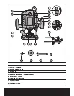
Page 8: ...SWITCH 2 LOCK ON BUTTON 3 HANDLE 4 DEPTH STOP BAR FIXING SCREW 5 PARALLEL GUIDE 6 TRIPLE DEPTH STOP 7 COLLET NUT 8 SPINDLE LOCK 0 1 2 3 4 5 6 7 1 2 11 12 13 1 2 3 15 16 4 12 5 6 7 8 9 18 19 20 21 10 11 13 14 17 ...

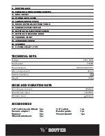
Page 9: ... 3 64m s2 ACCESSORIES 1 2 collet ready fitted 1pc 1 4 collet 1pc Vacuum adaptor 1pc Parallel guide 1pc Spanner 1pc Trammel point 1pc 30mm Guide bush 1pc 9 ROUTING BASE 10 PARALLEL GUIDE LOCKING SCREWS 11 DUST OUTLET 12 PLUNGE LOCK LEVER 13 CARBON BRUSH COVER 14 MICRO DEPTH ADJUSTMENT KNOB 15 VARIABLE SPEED SWITCH 16 DEPTH BAR ADJUSTMENT SCREW 17 DEPTH BAR MEASURE GUIDE 18 TRAMMEL POINT 19 30MM GUID...

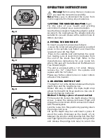
Page 10: ...router bit where this gap will be defined as the Maximum Free Shank Length The unit is provided with a 1 4 collet Simply remove the 1 2 collet from the spindle and replace with the 1 4 collet Please see further safety notes on router cutters at back of this booklet 3 ADJUSTING DEPTH OF CUT The depth of cut is the distance between the triple depth stop and the length stop bar Router bits vary in dep...

Page 11: ...depth stop bar to the calculated number and lock bar with the fixing screw Release the clamp lock lever the router will return to its original position Start Router as described in Starting the router section below Before proceeding carry out test cut on waste timber 4 MAKING FINE ADJUSTMENT TO CUT DEPTH To make fine adjustments turn the triple depth stop by loosening the centre screw lift the stop ...

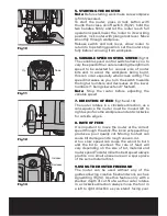
Page 12: ...ter before adjusting the variable speed 7 DIRECTION OF FEED fig15 and 16 The router rotates in a clockwise direction as a consequence the router must be moved left to right as you face the workpiece and anti clockwise for outside edges 8 RATE OF FEED It is important to move the router at the correct speed through the work The incorrect speed may produce a poor quality cut Moving too fast can cause ...

Page 13: ... guide and fasten it in place with the thumb screw Place the trammel point against the material Set the required radius by adjusting the shaft of the edge guide and tighten the edge guide locking screws Fixing router in required depth with lock lever Switch on the machine After releasing the plunge lock lever lower the machine slowly Cut grooves shoulders etc at a steady rate of feed holding the m...

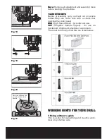
Page 14: ... Only use cutter bits with a shank that matches the collet used HSS High Speed Steel for softwood use TCT Tungsten Carbide Tipped for use on hardwood chipboard plastics or aluminium The most commonly used bits are listed below WORKING HINTS FOR YOUR DRILL 1 Using without a guide This is useful for signwriting and creative work User only shallow cuts Note the collar on the guide bush should be upwa...

Page 15: ...3 Always store your power tool in a dry place 4 Keep the motor ventilation slots clean 5 If you see some sparks flashing in the ventilation slots this is normal and will not damage your power tool 6 If the supply cord is damaged it must be replaced by a special cord or assembly available from the manufacturer or its service agent TROUBLESHOOTING 1 If your router will not operate check the power at ...

Page 16: ... with a fitted plug however if you should need to fit a new plug follows the instruction below IMPORTANT The wire in the mains lead are coloured in accordance with the following code Blue Neutral Brown Live The wire that is coloured blue must be connected to the terminal that is marked with the letter N The wire that is coloured brown must be connected to the terminal that is marked with the letter ...

Page 17: ...ing directives 89 336 EEC 93 68 EEC EMC Directive 73 23 EEC 93 68 EEC Low Voltage Directive 98 37 EC Machinery Directive Standards and technical specifications referred to EN 60745 1 2003 A1 2003 EN 60745 2 17 2003 EN 55014 1 2000 A1 2001 A2 2002 EN 55014 2 1997 A1 2001 EN 61000 3 2 2000 EN 61000 3 3 1995 A1 2001 2005 Authorised Signatory Date 03 15 05 Signature Name Peter Harries Screwfix Direct Lt...

Page 18: ......

Page 19: ...ROUTER ...

Page 20: ......

Reviews: