


23
22
USE
01
INTENDED USE
This product is intended for cutting wood and similar material e.g. MDF and chipboard,
plastic and metal using appropriate saw blades.
02
OPERATION
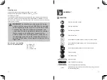
PENDULUM SELECTOR (E)
Adjust the pendulum speed according to the workpiece material and thickness.
Illustration
Position
Pendulum action
Application
0
off
fine cuts in thin
workpieces cutting
tight curves or circles
1
short
hard workpieces,
(e.g. steel &
chipboard)
2
medium
thick workpieces (e.g.
wood and plastics)
3
long
fast cuts in soft
materials (e.g.
softwood)cutting in
the direction of the
wood grain
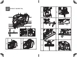
ANGLE ADJUSTMENT (F1, F2)
WARNING!
Always ensure the product is switched off and removed the
battery pack before carrying out any work on the product!
The base plate (13) can be adjusted to left or right 15°/30°/45° for bevel cutting. Turn the
base adjustment lever (12) to the right to loosen the base plate clamp. Move the base
plate (13) forwards so that the teeth on the plate no longer engage with the retaining
teeth and the plate can be tilted to the left or right. Tilt the base plate (13) to adjust
required cutting angle. Choose 15°/30°/45° or 0°, push the plate backwards so that the
teeth on the plate mesh with the retaining teeth. Turn back the base adjustment lever (12)
to the left to tighten the base plate clamp.
ON/OFF SWITCH (G)
Press the lock button (4) to the left then press the on/off button (5) to switch the product
on. To switch the product off just release the on/off button (5) and turn back the lock-
off button (4) When not in use, it is advised to return the lock button to the locked
position(fully right) to avoid accidental re-start.
SPEED CONTROL
The on/ off switch (5) is combined with a speed control. Adjust the speed directly with the
on/ off switch. The speed is controlled by how far the trigger switch is depressed.
AUTOMATIC LED WORK LIGHT (H)
The LED work light (18) will illuminate when the trigger switch is depressed slightly, and
will automatically turn off a short while after the trigger switch is released. This provides
additional light on the surface of the workpiece for operation in lower light situations.
BLOWER AND VACUUM (I)
Turn the blower switch (19) to the position “
” to blow away dust and chips in the
cutting area. Turn the blower switch (19) to the position“x
” when connected to a dust
extraction system or household vacuum.
NOTE:
Do not use blower when using vacuum extraction!
PARALLEL CUTTING (J)
Attach the parallel guide (17) to the product as described above and adjust to the desired
width.
Switch the product on and wait until it runs at full speed before placing it on the
workpiece.
Place the product laterally to the workpiece and use the parallel guide to guide the
product along the workpiece.