selected, all parameters will be set to zero, and will need to
be entered manually. Parameters entered while using batch
0 are never stored (i.e. the “0” batch is a scratch memory
location). Parameters for all other batches are stored, so the
next time that particular batch is called, those parameters will
be presented as defaults. If any parameters are edited, the
new values will be stored for the next time that batch is
entered. All batches that have parameters stored can be
edited by entering the desired batch number.
CREATING A NEW BATCH:
Enter the number on the last line of the batch prompt screen,
in this case 1. The first edit screen will appear:
Length units IN #1 (Use + or - key to change to mm)
Length 0.00
Length compensation 0
Quantity 0
The current batch number is shown beside the # at the top
right. The cursor will be flashing just before the in (inch),
indicating that the field is currently editable. In general, the
line being edited will display a blinking cursor. Press ENTER
to accept the default of inches, or press the “+” or “-“ key to
toggle to mm, for millimeters, then press ENTER to store
mm. Each time ENTER is pressed, the cursor advances to
the next parameter.
Enter a value for the length parameter. If ENTER is pressed
accidentally before a value is entered, a long error beep will
sound, otherwise the entered value will be stored. If a mistake
is made, press the BS key to back space over the entry. If the
enter key has been pressed, press the ESC key and start
over. All values entered so far will have been stored, so you
would only have to press ENTER until you returned to the
place where you wanted to make a change-the values would
not have to be entered again. Any value between .01 and
23,300 may be entered. This allows for 5 digits before the
decimal place and 2 digits after. In mm mode, only 1 decimal
place is allowed after the decimal point and 6 digits in front of
the decimal.
Due to variations in materials, pre-feed systems and belt
tension, actual cut length may vary from the inputted length
by a proportional amount. The WC601B incorporates a length
compensation feature to provide an easy adjustment in these
cases. The length can be compe/-1% to +/- 99% of
the inputted length. The length compensation display will
show (-) for a negative value. Example: If 10" (254mm) is
entered as the desired length, but the actual cut pieces
measure 9.8" (249mm), a length compensation of +2% will
increase the cut length by .200 (5mm) to the desired 10"
(254). The default is 0, or the “+” or “-” keys may be used to
add or decrease length compensation of plus or minus 1 -
99% of the inputted length. NOTE: Often it will not be known
if length compensation is needed until after a trial run is
completed. When programming a batch, leave the field at 0
and edit the batch later if necessary to add length compen-
sation. Once a value has been entered, or if the default of 0
is to be used, press ENTER. The length compensation will
remain with the batch program. An alternate, more accurate,
method would be simply to enter the desired cut length,
measure the error and add/subtract the error to/from the
targeted length (e.g. a desired 10.00” is entered into the
length parameter; a measured 9.82” is cut. The operator
compensates for this by adding 0.18” to the targeted cut
length value. The new cut length value becomes 10.18”).
ENTER THE QUANTITY OF CUT DESIRED - UP TO 999,999.
Rate Screen:
Feed Rate 3
#x
(Enter 1 thru 9, rate #3 is default.
x=current batch number)
Initial Rate 1500
Final Rate 8600
Acceleration 18
After the quantity is entered, the rate edit screen appears.
Press “+” or “-” to increment or decrement the feed rate value.
Alternately, the desired feed rate may be entered manually
(any number between 1 and 9). As the value is changed, the
rate values are updated to show what values are active for that
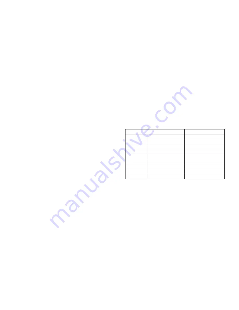
feed rate. The following table represents the maximum speed
at any feed rate of the feed belts:
NOTE: The slower the feed rate, the more accurate in length
the cut pieces will be. It is advised to start with the lowest feed
rate and check results, then adjust the feed rate if desired.
Cutter Screen:
Cutter Parameters
Cut Speed 6
(Enter 1 thru 9, 6 is default)
Cut Time 1.000 (Enter 0.1 to any number of seconds, 1 is default)
The cut speed controls the speed and pressure at which the
rotary blade cuts through the material. If material does not cut
completely through, increase the speed control. If cut is not
clean enough, decrease the speed control. The cut time can
be changed for materials of different hardness. Average cut on
times are from 0.5 second to 2 seconds. The blade speed and
cut time should be set as low as possible to give the best
possible cut. There are 9 cut speeds that allow incremental
adjustment of the rotary speed of the cut head (typically 750
RPM to 1900RPM).
After the Cut Time is entered, the display under “Cut Time
x.xxx” will show: “Press Run to Start”. Press RUN or ENTER
to begin the cutting cycle of the tubing cutter.
Run Screen:
Feed Rate # Linear Speed (in/sec) Linear Speed (mm/sec)
1
5.7
144
2
8
203
3
12.2
309
4
16.6
421
5
20.8
528
6
25.1
637
7
29.3
744
8
33.4
848
9
39.8
1011


