


Epson WF-7620 / WF-7610 / WF-7110 Series
Revision B
Disassembly/Reassembly
Detailed Disassembly/Reassembly Procedure for each Part/Unit
40
Confidential
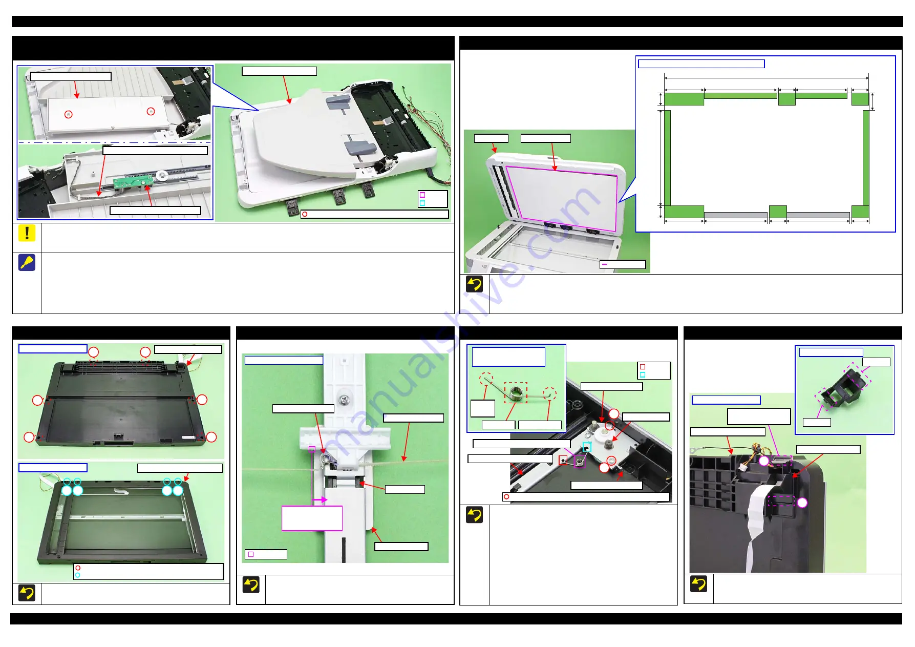
ADF Paper Support Cover/Paper Support Encoder Sensor/ADF Paper Support Assy
(WF-7620/7610 Series)
On the ADF Paper Support Assy for the WF-7620/7610 Series, the Paper Support Encoder Sensor for paper width detection is mounted. Because the
ADF Paper Support Assy is connected with the ADF unit by the Paper Support Encoder Sensor cable, release the routing of the cable following the
disassembly procedure below.
Remove the ADF Paper Support Cover/Paper Support Encoder Sensor/ADF Paper Support Assy as follows.
1. Release the dowels (x2) and shafts (x2) on the ADF Paper Support Assy, and turn the assy upside down.
2. Remove the screws (x2) that secure the ADF Paper Support Cover, and remove the ADF Paper Support Cover.
3. Remove the screw that secures the Paper Support Encoder Sensor, and disconnect the Paper Support Encoder Sensor cable from the connector on
the Paper Support Encoder Sensor, then remove the sensor.
4. Release the routing of the Paper Support Encoder Sensor cable, then remove the ADF Paper Support Assy.
C.B.P-TITE SCREW 3x8 F/ZN-3C (6
±
1
kgf
·
cm)
ADF Paper Support Assy
Dowel
Shaft
ADF Paper Support Cover
Paper Support Encoder Sensor cable
Paper Support Encoder Sensor
Document Pad (WF-7620/7610 Series)
Attach double-sided tape on the pieces of sponge on the Document Pad indicated in green in the figure above, and attach the Document Pad to the
ADF Unit.
After attaching the Document Pad, make sure the Document Pad is attached within the standard line shown above and the sponge pieces are not
sticking out from the Document Pad.
Standard line
ADF Unit
20 mm
20 mm
262 mm
26 mm
147.5 mm
147.5 mm
168.5 mm
127 mm
30 mm
30 mm
30 mm
30 mm
75 mm
438.5 mm
75 mm
Sponge positions on back of Document Pad
Document Pad
Scanner Housing Upper Assy (WF-7620/7610 Series)
Tighten the screws in the order indicated in the figure above.
Scanner Housing Lower
Bottom of Scanner Unit
1
2
3
4
6
5
7
C.B.P-TITE SCREW 3x10 F/ZB-3C (6
±
1 kgf
·
cm)
Scanner Housing Upper Assy
9
8
10
C.B.P-TITE SCREW 3x10 F/ZN-3C (6
±
1 kgf
·
cm)
Upper of Scanner Unit
Scanner Carriage (WF-7620/7610 Series)
If the Torsion Spring 43.6 has come off from the Scanner Timing
Belt, attach it to the CIS module side inner than this projection on
the Scanner Carriage.
Scanner Carriage
Torsion Spring 43.6
Scanner Timing Belt
Protrusion
Attach to CIS module
side inner than this
projection.
Back of Scanner Carriage
CIS Module
Scanner Motor Assy (WF-7620/7610 Series)
Tighten the screws in the order indicated in the figure above.
Secure the scanner grounding wire and the Scanner Motor Assy
together with the screw 2 shown above.
When attaching the Scanner Rail Strengthen Plate Grounding
Spring, follow the procedure below.
1. Insert the spring leg 1 of the Scanner Rail Strengthen Plate
Grounding Spring into the hole of the Scanner Rail Strengthen
Plate.
2. Attach the section A of the Scanner Rail Strengthen Plate
Grounding Spring to the dowel of the Scanner Housing Lower.
3. Attach the spring leg 2 of the Scanner Rail Strengthen Plate
Grounding Spring to the cutout of the Scanner Motor Plate.
Spring
Foot 1
Section A
Scanner Rail Strengthen
Plate Grounding Spring
Spring Foot 2
Scanner Motor
Scanner Rail Strengthen Plate
Dowel of Scanner Housing Lower
Scanner grounding wire
Cutout
Scanner Motor Plate
C.B.P-TITE(S-P1) SCREW 3x12 F/ZN-3C (6
±
1 kgf
·
cm)
1
2
Hole
Scanner FFC Cover (WF-7620/7610 Series)
When installing the Scanner FFC Cover, install it with the hook A
of the cover to the rear of the printer, and secure the cover to the
Scanner Housing Lower in the order of hook B and hook A.
Scanner FFC Cover
Scanner Housing Lower
Hook A
Scanner FFC Cover
Hook B
Install with the hook
A in this way.
2
1
Bottom of Scanner Unit
Summary of Contents for WF-7110 Series
Page 8: ...5 2 Protection for Transportation 86 5 2 1 Securing the CR Unit 86 ...
Page 9: ...Confidential CHAPTER 1 TROUBLESHOOTING ...
Page 23: ...Confidential CHAPTER 2 DISASSEMBLY REASSEMBLY ...
Page 52: ...Confidential CHAPTER 3 ADJUSTMENT ...
Page 75: ...Confidential CHAPTER 4 MAINTENANCE ...


