


Rev. B
Disassembly and Assembly 4-9
TM-U220 Type A Service Manual
Confidential
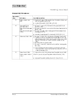
DIsassembly Procedures
Reassembly
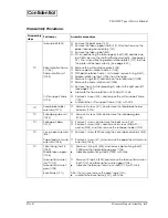
steps
Part names
Assembly procedures
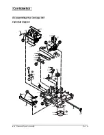
❶
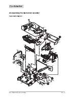
Ribbon frame
assembly (519)
❏
Remove the ribbon frame spring (1022).
❏
Remove 1 E-ring 4 (E03), and remove the ribbon frame assembly
(519).
❏
After this, you can remove the print head unit (503).
6
Lubricate the carriage sub assembly (1025) with O-13.
❷
Carriage sub
assembly (1025)
Carriage belt (507)
Head FFC (521)
❏
Remove the right and left adjustment roller shaft holders (506).
❏
Pull out the carriage shaft (1027).
❏
Remove the head FFC (521) from the carriage sub assembly
(1025).
❏
Loosen 2 screws (S12, S14) securing the belt tension plate sub
assembly (1086).
❏
Remove the carriage belt (507), together with the carriage sub
assembly (1025).
❏
Remove the belt tension plate sub assembly (1086).
❏
Remove the head FFC (521).
Note for replacing the adjustment roller shaft holders (See page 4-22):
When you need to remove the adjustment roller shaft holders (506),
you must replace each holder with a new part. This is necessary
because the part changes when you remove it.
Note for attaching the carriage sub assembly (1025) (See page 4-24):
When you reassemble the carriage sub assembly (1025), you also
need to adjust the unit’s platen gap. (See page 5-5.)
Note for attaching the carriage belt (507) (See page 4-23):
When you reattach the carriage belt, adjust its tension. (See page 5-
6.)
Confirm the head FFC (521) is connected correctly. (See page 4-23.)
6
Lubricate the carriage sub assembly (1025) with O-13.
6
Lubricate the belt tension plate sub assembly (1086) with G-36.
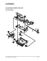
❸
Carriage guide plate
(1030)
Carriage guide plate
sub assembly (1026)
❏
Remove 2 screws (S11), and remove the carriage guide plate
(1030).
❏
Remove the carriage guide plate sub assembly (1026).
6
Lubricate the carriage guide plate (1030) and the belt tension
plate sub assembly (1086) with G-36.
❹
Ribbon drive plate
sub assembly (517)
Ribbon middle gear
(512)
Ribbon take-up gear
sub assembly (516)
Belt drive pulley (505)
❏
Remove 1 E-ring 2.3 (E02), and remove the ribbon drive plate sub
assembly (517).
❏
Remove the ribbon middle gear (512).
❏
Remove the ribbon take-up gear sub assembly (516).
❏
Remove 1 E-ring 3 (E01), remove the belt drive pulley (505).
❺
Carriage motor sub
assembly (1034)
❏
Remove 2 screws (S09), and remove the carriage motor sub
assembly (1034).
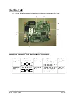
❻
HP board assembly
(518)
❏
Remove 1 screw (S11), and remove the HP board assembly (518).
When replacing the HP board assembly (518), you need to
remove the solder. Resolder when attaching the HP board
assembly (518). (See page 4-24.)
Base frame (1011)
After this, you can remove the base frame (1011).
6
Lubricate the base frame (1011) with G-15 and G-36.


