


Rev. B
Disassembly and Assembly 4-5
TM-U220 Type A Service Manual
Confidential
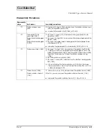
Disassembly Procedures
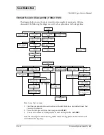
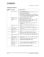
Disassembly
steps
Part names
Disassembly procedures
❶
Roll paper cover
assembly (119)
❏
Open the roll paper cover assembly (119).
❏
Push and take out the open lever shaft (1001), and then
remove 1 screw (S02).
❏
Release the hooks in 3 positions as shown in the diagram, and
remove 2 screws (S03).
❏
Remove the roll paper cover assembly (119).
When removing the roll paper cover assembly, release the 3
hooks. (See page 4-16.)
❷
Top case (108)
❏
Remove 2 screws (S03).
❏
Open the ribbon cover (109).
❏
Remove the top case (108) and ribbon cover (109) together.
When attaching the top case be sure not to catch the cables
in the frame. (See page 4-19.)
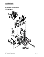
❸
Back case (130)
Paper take-up gear
assembly (1110)
Take-up belt (523)
❏
Remove 2 screws (S02). After that, remove the back case (130).
❏
Remove the paper take-up gear assembly (1110).
When attaching the paper take-up gear assembly (1110), be sure
that the take-up gear shaft (139) is attached from the correct
direction.
❹
I/F circuit board unit
(122)
❏
Remove the I/F circuit board unit (122).
❺
Bottom plate (1004)
❏
Remove 4 screws (S03),and remove the bottom plate (1004).
❻
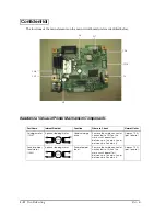
Main circuit board unit
(201)
❏
Remove connectors attached to the main circuit board unit
(201).
❏
Remove 4 screws (S01), and remove the main circuit board unit
(201).
When reattaching each cable to the main circuit board, be
sure each cable is attached correctly. (See page 4-27.)
Sub circuit board unit
(123)
❏
Remove 2 screws (S01), and remove the sub circuit board unit
(123).
❼
Autocutter unit (113)
❏
Remove 2 screws (S02), and remove the autocutter unit (113).
When attaching the autocutter, confirm that the cutting
pattern is selected correctly (partial cut or full cut). (See page
5-4.)
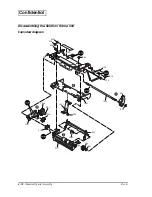
❽
Bottom frame
assembly (1085)
❏
Remove 4 screws (S02), and remove the bottom frame
assembly (1085). After that, remove the mechanism assembly
(120).