Epson Stylus Pro 9000 - Print Engine Service Manual Download Page 128

EPSON Stylus Pro 9000

Adjustments

128

COUNTER CLEAR

This function resets all the counters stored in memory on the Main Board to 
their original condition. Remove the old ink cartridges before resetting the 
counters; when you turn on the printer, the printer prompts you to install new 
cartridges.

If you need to reset counters individually, see 

Maintenance Mode 2

 on 

page 17.

Note *: "1" means the flag is set, and the next time power is turned on the printer will 

perform an initial ink charge.
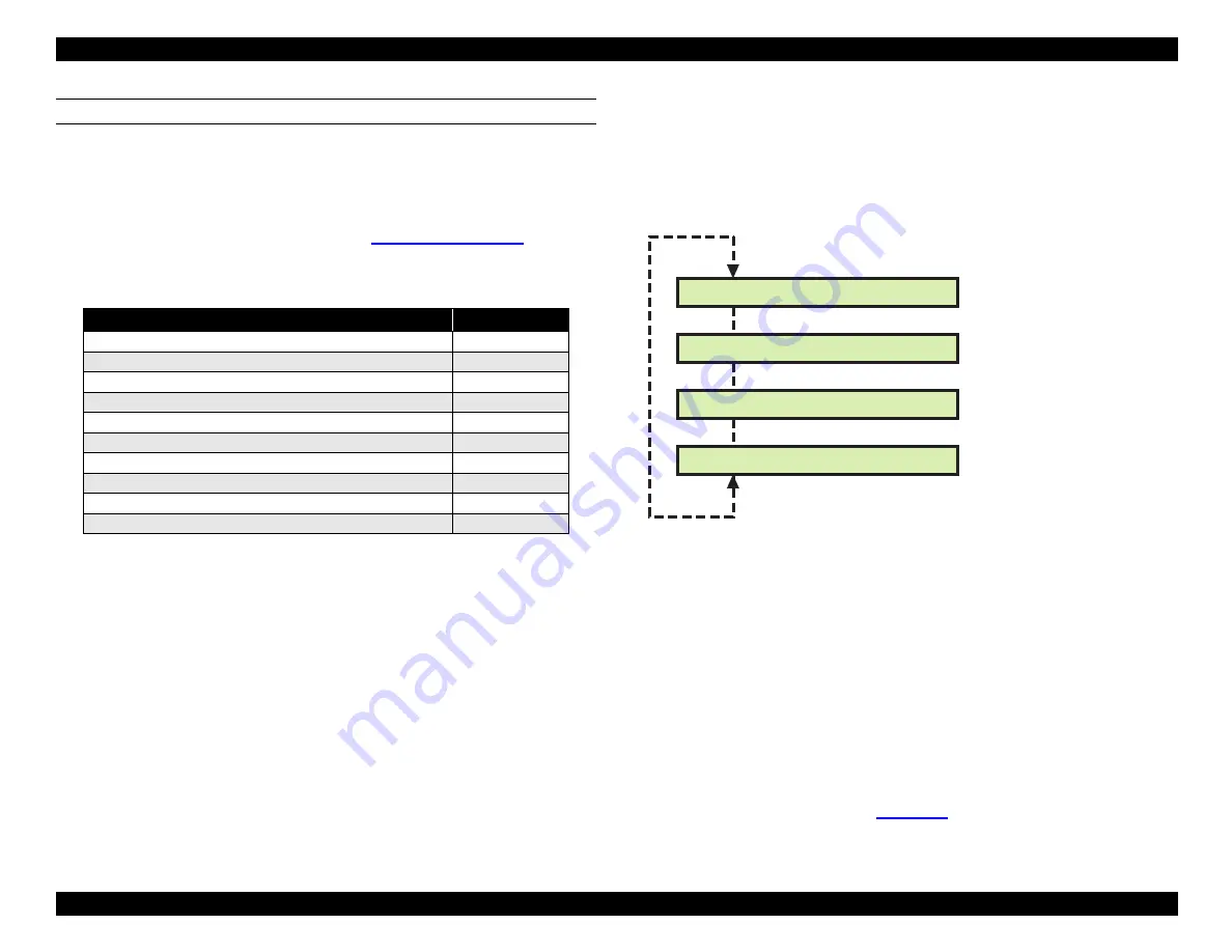
5.3.5  Cleaning menu

Using this menu, you can select a cleaning mode and start that cleaning 
operation. You can also cause the printer to perform the initial ink charge 
operation without resetting the initial ink charge flag.

Std. KK0 (CL1)
Normal cleaning cycle

Volume of ink cleared = low

Std. KK1 (CL1’)
Strong cleaning cycle

Volume of ink cleared = medium
Rubbing = off

Std. KK2 (CL2)
Strong cleaning cycle

Volume of ink cleared = high
Rubbing = on

Init. Fill

Perform initial ink charge sequence

5.3.6  Print menu

The Print menu performs the same functions as the "Test Print" option on the 
Adjustment menu. For details, see 

Test Print

 on page 127.

Table 5-11.  Counters Reset by "Counter Clear"

Counter

Reset Value

Protection Counter A/B (for waste ink pads)

0

Ink Volume Counter Rb/ Ry/ Rx Rz

0

Consumed Ink Counter Cb/ Cy/ Cm/ Cc/ Cml/ Ccl

0

Power Cutoff Timer T2

0

Accumulated Prints Timer

0

CL Timer

0

CL Timer 3

0

CL Flag

0

Initial Charge Flag

1*

Periodic Pseudo-Vacuum Flag

0

[SelecType]

[Paper Source]

Cleaning: Std.     KK0

Cleaning: Std.     KK1

Cleaning: Std.     KK2

Cleaning: Init. Fill

Performs the initial ink 

charge operation

[Enter]

Summary of Contents for Stylus Pro 9000 - Print Engine

Page 1: ...EPSONStylusPro9000 Wide Format Professional Inkjet Printer TM PRO9000 ...

Page 2: ...ollow these step by step instructions to disassemble and assemble the printer Refer to the Maintenance section of this chapter when you need to replace the Waste Ink Pads and other consumable parts CHAPTER 5 Adjustments When you remove or replace parts read the beginning of this chapter to find out which adjustments are required and how to perform them CHAPTER 6 Maintenance Follow these routine in...

Page 3: ...s losses costs or expenses incurred by purchaser or third parties as a result of accident misuse or abuse of this product or unauthorized modifications repairs or alterations to this product Epson America Inc shall not be liable against any damages or problems arising from the use of any options or any consumable products other than those designated as Original EPSON Products or EPSON Approved Pro...

Page 4: ...tenna Increase the separation between the equipment and receiver Connect the equipment into an outlet on a circuit different from that to which the receiver is connected Consult the dealer or an experienced radio TV technician for help WARNING The connection of a non shielded equipment interface cable to this equipment will invalidate the FCC Certification of this device and may cause interference...

Page 5: ...until instructed to do so When the power supply cable must be connected use extreme caution in working on the power supply and other electronic components CAUTION 1 Repairs on EPSON products should be perfomed only by an EPSON certified repair technician 2 Make certain that the source voltage is the same as the rated voltage listed on the serial number rating plate If the EPSON product has a prima...

Page 6: ...e Mechanism 22 Paper Feed Mechanism 22 Ink System 23 Circuit Boards 23 Operation 24 Carriage Mechanism 24 Carriage CR Guide Rail 24 Platen Gap PG Mechanism 24 Paper Width Sensor 25 Carriage Motor and Position Control 26 Cutter Mechanism 27 Printheads 27 Paper Feed Mechanism 28 Paper Feed Motor and Rollers 28 Paper Feed Sensors 29 Paper Suction Fan 30 Paper Width Determination Left and Right edge D...

Page 7: ...s 71 Removing the Carriage Motor Assembly 75 Removing the PF Motor Assembly 76 Removing the Platen Gap Adjustment motor 78 Removing the Platen Gap Home Position Sensor 78 Removing the Cover open Sensors 79 Removing the Paper Thickness Sensor 80 Removing the Rear Paper Sensor 80 Removing the Front Paper Sensor 81 Removing the Paper Release Sensor 81 Removing the Carriage Home Position Sensor and En...

Page 8: ...ead Gap Timing 123 Flush Point Right and Left Adjustment 124 Feed Adjustment 124 Top Bottom Margin Adjustment 125 Rear Sensor Position Adjustment 126 Test Print 127 Clean Head Drain Ink 127 Counter Clear 128 Cleaning menu 128 Print menu 128 Parameter menu 129 Initialize 129 Update 129 Mechanical Adjustments 130 Carriage Cover Height Adjustment 130 Cutter Position Adjustment 131 Carriage Belt Tensi...

Page 9: ...ansporting the Printer 155 Before Shipping 155 After Shipping 155 Specifications 156 Mechanical 156 Safety Approvals 157 CE Marking 157 Electrical 158 Environmental 158 Ink Cartridge 158 Controller 159 Cutter 159 Paper 160 Paper Release Lever 162 Interface 162 Parallel interface 164 Nibble Mode 166 ECP Mode 166 Type B Interface Optional 168 Interface selection 168 Initialization 169 Jumper and DIP...

Page 10: ... PRINTERBASICS ...

Page 11: ...ormal paper approx 30 minutes 720 720 dpi quality on A0 glossy paper approx 55 minutes 1440 720 dpi superfine on A0 glossy paper Low operating costs 6 separate ink cartridges so only the empty ink cartridge is replaced Auto Rotate feature saves paper by automatically rotating an image if the width is shorter than the height Alternative interface compatibility IEEE 1284 bidirectional parallel inter...

Page 12: ...m feed of 20 cm when the button is pressed once 1 27 cm second paper feed for 2 seconds after key is pressed 7 62 cm second paper feed if pressed for over 2 seconds Power Operate Sheet Paper Out Roll Cutter Off Roll Auto Cut Cleaning 3 sec Enter Cut Eject _ Paper Feed Item Paper Source SelecType Reset 3 sec Pause Ink Out K C LC M LM Y LCD Display Table 1 1 Operation in Normal Mode Button Second fu...

Page 13: ...tion at Power On Button Second function Function Power Pause Reset Maintenance Mode See Maintenance Mode on page 17 SelecType Cut Eject Enter Paper FeedU Paper FeedD Paper Source Item Cleaning Paper Source Paper FeedD Cut Eject Maintenance Mode 2 See Maintenance Mode 2 on page 17 Paper Source Cut Eject Cleaning Firmware Update Mode See ROM Backup and Updating on page 105 Paper FeedD Cut Eject Clea...

Page 14: ...ble 1 5 Printer Setting Menu Message Item Explanation PLATEN GAP AUTO Adjusts the platen gap Normally leave set to AUTO THICK PAGE LINE ON When AUTO CUT OFF is selected on the control panel this setting determines whether a line for manual cutting is printed OFF INTERFACE AUTO Determines which interface the printer checks for data AUTO continuously checks all interfaces and is good for normal use ...

Page 15: ...e amount of ink left or the component life as follows E F full or full life remaining E F full or life remaining E F full or life remaining E F full or life remaining E F nearly empty or service life near end E F empty or service life ended Table 1 7 Printer Status Menu Message Explanation VERSION number Shows the firmware version INK LEFT C Amount of cyan ink remaining INK LEFT M Amount of magent...

Page 16: ...istered number up to 17 DRYING TIME 0MIN Determines the length of time the printer allows the ink to dry When printing on roll paper the printer will wait the specified time after printing Use the or to select the registered number up to 30MIN Table 1 9 Cutter Replacement Menu Step Message Item Explanation 1 CUT REPLACE EXEC Prepare a replacement cutter 2 OPEN LOWER COVER Open the front cover 3 RE...

Page 17: ... Maintenance Mode 2 Press the Paper Source Cut Eject and Paper FeedD buttons while turning on the printer C A U T I O N The operations described in this section are for service and support only Avoid sharing this information with the end user Table 1 11 Maintenance Mode Menu Message Menu Item Explanation HEX DUMP PRINT Print data printed in hexadecimal form LANGUAGE ENGLISH PORTUGUESE SPANISH GERM...

Page 18: ...jam Pause On Printer ready Flashing Performing head cleaning Printer is in ink drying phase Performing ink charging operation Ink Out Y On Ink out also occurs if no or wrong cartridge is installed Flashing Ink low Ink Out LM On Ink out also occurs if no or wrong cartridge is installed Flashing Ink low Ink Out LC On Ink out also occurs if no or wrong cartridge is installed Flashing Ink low Ink Out ...

Page 19: ...en Auto Cut is selected PAPER NOT STRAIGHT Paper slipped and fed into the printer at an angle Printing stops PAPER OUT No paper is loaded or paper has run out Cut paper did not fall off The paper detect sensor may have dust or grime blocking its operation PAUSE Pause state PRESS PAUSE BUTTON Press Pause to continue PRINTING Printer is receiving data PUSH LEVER DOWN Paper release lever is in the re...

Page 20: ...41222 36 in 914 mm wide 16 4 ft 5 m long S041223 44 in 1 118 mm wide 82 ft 25 m long Matte roll paper S041221 36 in 914 mm wide 82 ft 25 m long S041220 44 in 1 118 mm wide 82 ft 25 m long Photo quality ink jet paper S041079 A2 S041068 S041045 A3 S041069 S041043 A3 Wide B S041070 S041044 B Photo paper S041142 A3 S041143 A3 Wide B S041156 B Photo quality glossy film S041073 A3 S041074 A3 Wide B S041...

Page 21: ... TECHNICALOVERVIEW ...

Page 22: ...anism on page 24 Figure 2 1 Carriage Mechanism PAPER FEED MECHANISM For more information see Paper Feed Mechanism on page 28 Figure 2 2 Paper Feed Mechanism Guide Rail HP Sensor Encoder Carriage Cover Open Sensor interlock switch CR Motor Roll Paper Holders Paper Pressure Rollers Paper ThicknessSensor Rear Paper Sensor PF Motor Paper Feed Roller Paper Suction Fans Front Paper Sensor Paper Release ...

Page 23: ...4 Figure 2 3 Ink System CIRCUIT BOARDS For more information see Control Circuit on page 37 Figure 2 4 Circuit Boards I H Assembly Flushing Box L Waste Ink Pads Pump Assembly Wiper Cleaner Blade Cap Assembly CR Lock Flushing Box R Waste Ink Pads R Power Supply Board Main Board C277MAIN Control Panel Relay Board ...

Page 24: ...d relies on the printer frame for its stability As shown in Figure 2 5 the Carriage attaches to the CR Guide Rail with eight bearings and the carriage in turn holds the subcarriage The subcarriage holds the printheads PLATEN GAP PG MECHANISM Unlike previous models the Stylus Pro 9000 uses a special system to ensure that the distance between the printhead nozzles and paper remains the same for all ...

Page 25: ...paper is loaded the flag is forced forward out of the sensor area Sensor signal ON at 0 7 V or less Normal or thin paper Sensor signal OFF at 2 4 V or more Thick paper PG Sensor This light reflecting sensor detects whether the subcarriage is in the thick paper position or normal paper position The PG Gear rotates with the PG Cam and the PG Sensor determines the subcarriage s position from the posi...

Page 26: ...al to 180 dpi For every band the Linear Encoder passes over it sends a print timing pulse to the software servo system The software servo forms a closed loop with the CR motor and Encoder Sensor It receives feedback from the Encoder Sensor and adjusts the current to the CR motor to maintain constant carriage speed Carriage Speed and Acceleration Carriage Speed The carriage speed during printing is...

Page 27: ...e left edge 2 The cutter cuts from several centimeters inside the right edge to the right edge 3 The cutter cuts the remaining center portion from right to left Figure 2 8 Cutter Mechanism PRINTHEADS The printheads are the same type used in the EPSON Stylus Pro 5000 and are installed in the same way Three levers are provided to make sure the heads are lined up vertically and that neither head lean...

Page 28: ... Feed Roller and releases any loaded paper The Paper Feed Roller Assembly is made up of three equal lengths of rollers and their coupling The PF Motor uses a DC motor which has a built in optical rotary encoder The encoder sends signals to the software servo system which regulates the speed of the motor Motion is transferred through a timing belt to the Speed Reduction Gear which improves the accu...

Page 29: ...ched to the back side of the Lower Paper Guide and detects the rear edge bottom or trailing edge of the paper Paper Release Lever Position Sensor The Paper Release Lever is located on the right side of the printer and the sensor attaches to the bottom of the lever inside the right side frame This sensor s signal is ON when the lever is in down which allows the printer to print Figure 2 10 Paper Fe...

Page 30: ...UP Paper Out if Paper Release Lever DOWN Level 2 medium User continues loading paper Rear Paper Sensor ON Front Paper Sensor ON Load Paper if Paper Release Lever UP Press Pause Button if Paper Release Lever DOWN Fan goes from Level 3 high to Off and then back to Level 3 high during paper setting sequence User lowers Paper Release Lever and presses Pause or user allows several seconds to pass after...

Page 31: ...here the left edge should be if the paper is loaded correctly 5 The Paper Width Sensor checks for paper If paper is not detected go to step 6 otherwise report Reload Paper error To establish sensor signal level 6 The printer registers the sensor s no paper OFF signal level Right Paper Edge Printable Area Left Paper Edge To determine position of left edge 7 The carriage moves to the left paper edge...

Page 32: ...f 200 mm 2 The Front Paper Sensor checks for paper If during reverse feeding it detects the top edge of the paper go to step 3 otherwise report Reload Paper error To determine top left edge position 3 Carriage moves from home position to 30 mm inside left edge of paper 4 Printer reverse feeds 200 mm max 5 The Paper Width Sensor checks for paper If during reverse feeding it detects the top edge of ...

Page 33: ... occurs To avoid paper loading errors make sure the paper s left edge near HP is lined up with the vertical line of holes in the Lower Paper Guide Paper loaded within 10 mm of the center of the vertical line of holes in the Lower Paper Guide is considered in the printable zone however paper loaded outside that 10 mm zone causes an error 2 2 3 Carriage Lock Mechanism The printer uses an electromagn...

Page 34: ...ers from accidently installing a color ink cartridge in the wrong slot the cartridges have slightly different designs Another important feature of the ink cartridge holders is the ink valve which is located on the outer sides of the ink cartridge holders It can be used to shut off the flow of ink during printer transportation The valve is closed when the user turns the valve to the CLOSE position ...

Page 35: ...cal sensor microswitch is at the bottom of all six ink cartridge slots and detects when ink is running out When the I C is nearly empty the switch open When the I C is not low normal the switch closed Ink ID sensor This optical sensor is located on the side of all six ink cartridge slots and detects which market the cartridge is for Although not currently implemented the sensor can also detect the...

Page 36: ...s open relays that control current to the CR motor and PF motor cut off the flow of current As shown in Figure 2 15 a bypass capacitor prevents current spikes from damaging drivers and other circuitry when the relays shut off Figure 2 14 Cover Open Sensor Figure 2 15 Relay Circuit Between Cover Open Sensors and Printer Motors Front Cover Cover Open Sensor Driver Driver CR Motor PF Motor Front Cove...

Page 37: ... Board Main Components Name Code Location Function CPU C90A08CA SH7043 IC8 32 bit RISC CPU Clock speed 33MHz 128KB PROM internal ASIC E05B61AA IC13 Regulates print data Command handling Rasterizer image data handling Head drive regulation DAC Print timing regulation Memory DRAM SRAM I F Circuit Control Parallel interface IEEE1284 Macintosh Serial interface Type B ASIC TE7751 IC20 Regulates Motor P...

Page 38: ... TROUBLESHOOTING ...

Page 39: ...ith print quality such as missing dots or lines misaligned vertical lines or banding faint white lines see Print Quality Troubleshooting on page 49 3 2 Troubleshooting Using LCD Error Messages The EPSON Stylus Pro 9000 performs self diagnostic tests using the data supplied by its sensors and if an error is detected by one or more sensors an error message appears on the control panel display When t...

Page 40: ... page 43 00010008 Servo interrupt watchdog time out error page 43 00010009 System interrupt watchdog time out error page 43 0001000A CR origin sensor malfunction page 43 0001000C PG origin sensor malfunction page 43 0001000D Cover sensor malfunction 00 page 44 0001000E Cover sensor malfunction 01 page 44 0001000F CR motor PWM output error page 44 00010010 PF motor PWM output error page 44 Service ...

Page 41: ...s reached 2 5 million passes which indicates that the Ink Tubes should be replaced due to excessive wear and tear Solution Replace the Ink Tubes as explained in Removing the Ink Tubes on page 92 SERVICE REQ 00010000 Problem PF motor encoder check error When the PF motor turns the printer checks the rotary encoder output signals to make sure the motor is turning at the correct speed and distance If...

Page 42: ... Main Board SERVICE REQ 00010004 Problem CR motor linear encoder check error When the CR motor turns the printer checks the linear encoder output signals to make sure the motor is turning at the correct speed and distance If the encoder doesn t send the correct output data an error occurs Solution Make sure there is nothing blocking the carriage If that does not solve the problem check the linear ...

Page 43: ...e CR motor Replace the Main Board SERVICE REQ 00010008 Problem Servo interrupt watchdog time out error due to motor drive control related error Solution Replace the Main Board SERVICE REQ 00010009 Problem System interrupt watchdog time out error due to sensor related error Solution Replace the Main Board SERVICE REQ 0001000A Problem CR origin home position sensor malfunction Solution Check the HP ...

Page 44: ...E REQ 00020002 SRAM ERROR SERVICE REQ 00020003 DRAM ERROR SERVICE REQ 0002000B MAIL BOX RECEIVING ERROR Problem Unusual condition detected Solution Write down the error code and then turn the printer off and back on to confirm that the error recurs If the error recurs replace the Main Board For Service Req 00020003 DRAM error replace the SIMM installed in CN19 and then check whether the error recu...

Page 45: ...aper is properly loaded there may be something on the Rear Paper Sensor s surface Clean the sensor s surface hole in the Upper Paper Guide with a clean dry cloth or using compressed air LOAD XXX PAPER Problem The selected paper source according to the remote PP command and the paper type selected on the control panel do not match Solution Load the correct paper or change the panel setting to match...

Page 46: ...more time to dry than the freshly deposited ink Solution Close the cover as soon as possible If the cover is fully closed when this error occurs make sure the left and right cover open sensors are correctly installed and are operating properly PAPER NOT CUT Problem The paper that was supposed to be cut was not cut completely or the paper was cut but is still in front of the Front Paper Sensor Solu...

Page 47: ...ean cut the paper for 5 and 6 above Cut off the ejected portion of the paper and reload the rest of the paper For paper that is automatically cut lift up the Release Lever the Load Paper message appears fix the position of the paper and lower the Release Lever If you select the Roll Auto Cut setting you can cut off the ejected portion of the paper using the Cut button If the error recurs even afte...

Page 48: ...nditions Thick paper is loaded when an automatic cleaning operation is supposed to begin The printer attempts to print on thick paper when an automatic cleaning operation is supposed to begin You turn on the printer and the thick paper is loaded You attempt to perform a manual cleaning operation when thick paper is loaded Solution Remove thick paper and push the Release Lever down this causes the ...

Page 49: ...rces out the old ink that is clogging the nozzles 3 If the cleaning operation does not clear the clogged nozzles check the following Is there damage to or foreign material in the rubber seal of the Capping Assembly Is the Capping Assembly valve operating normally Is the Capping Assembly retention spring working properly Are the ink tubes and pipes between the ink cartridges and printheads properly...

Page 50: ... may be defective Turn the printer on and perform the capping position adjustment See Cap Position Adjustment on page 116 Turn the printer off turn it back on and then run a cleaning cycle as described in Cleaning menu on page 128 While the cleaning cycle is running watch the end of the tubing leading to the Flushing Box Right If ink does not flow through the tubing replace the Pump Mechanism If t...

Page 51: ...OR MARRED PRINTOUT REVERSE SIDE The reverse side of the paper can become smudged or marred if there is ink on the printer parts Make sure there is no ink on the following parts and if there is ink wipe off the affected parts Sub platen Paper Feed Roller Paper Pressure Rollers Lower Paper Guide If the problem is not caused by ink on these parts most likely the paper jammed in the printer or curled ...

Page 52: ...ten gap CN12 Relay Board Paper Thickness Sensor Poor print quality or little or no ink output due to priming or cleaning problem CN19 white cable Relay Board Pump Motor May see Paper Not Cut error Paper doesn t cut CN6 Printhead Board Cutter Solenoid CN10 Main Board PSB Fan Left CN15 Main Board Relay Board CN3 CN26 Main Board PSB Fan Right Ink Compart Open C M K Solid CN21 Main Board Ink Housing L...

Page 53: ...Board CR Motor Service Req 00010004 Carriage slams right CN2 Printhead Board CR Linear Encoder Sensor Service Req 00010004 Carriage slams right CN6 ribbon cable white Relay Board Printhead Board Service Req 0001000A CN4 Printhead Board Home Position Sensor Service Req 0001000C CN17 Relay Board Platen Gap Origin Sensor Service Req 0001000C CN18 light blue cable Relay Board Platen Gap Motor Service ...

Page 54: ... DISASSEMBLY ASSEMBLY ...

Page 55: ...four people are needed For safety reasons the front cover s position up or down is detected by the cover open sensors located under the left and right side covers of the printer Do not block or modify these sensors If ink gets on your hands wash them thoroughly with soap and water If ink gets in your eyes rinse them immediately with water Because the main board includes a lithium battery for memor...

Page 56: ...5 mm PF motor and CR belt 4 0 and 5 0 mm for setting up printer only Table 4 2 Screws Type Color Description CP W2 M3x6 black Crosshead Pan spring washer flat washer CP W2 M4x12 silver Crosshead Pan spring washer flat washer CP W2 M4x6 silver Crosshead Pan spring washer flat washer CP W2 M4x12 black Crosshead Pan spring washer flat washer CP W2 M3x8 silver Crosshead Pan spring washer flat washer C...

Page 57: ...page 67 Removing the Front Paper Sensor on page 81 Replacing the Printheads on page 71 Main Board Removal on page 66 Removing the Rear Paper Sensor on page 80 Removing the Platen Gap Adjustment motor on page 78 Removing the Platen Gap Home Position Sensor on page 78 Removing the Paper Thickness Sensor on page 80 Removing the Cover open Sensors on page 79 Removing the PF Motor Assembly on page 76 M...

Page 58: ... Removal Follow the steps below to remove the printer s housing MAINTENANCE COVER REMOVAL 1 Open the Front Cover 2 Remove 2 screws CP W2 M3x6 and then remove the Maintenance Cover Figure 4 3 Maintenance Cover Removal Roll Cover Upper Paper Guide behind Top Cover Right Side Cover Maintenance Cover Top Cover Lower Paper Guide Front Cover Left Side Cover Right Joint Cover CP W2 M3x6 screw x2 ...

Page 59: ... Top Cover Removal 3 Lower the Paper Release Lever 4 Slide the Top Cover slightly forward to free it from its mounting brackets in back Then lift the Top Cover from the rear tilting it forward and lift it away from the printer Mounting brackets lower C A U T I O N When removing the Top Cover avoiding catching its rear edge on the Paper Thickness sensor which may knock it out of adjustment The sens...

Page 60: ...2 Remove the seven screws five silver CP W2 M4x12 and two black CP W2 M4x12 securing the Left Side Cover and remove the Left Side Cover Repeat for the Right Side Cover NOTE The control panel is attached to the Right Side Cover When removing the Right Side Cover detach the flat cable from the control panel Figure 4 6 L R Side Cover Inner Screw Location Figure 4 7 L R Side Cover Outer Screw Location...

Page 61: ...t side of the printer and then remove the damper assembly Figure 4 8 Removing the Damper Assembly 2 The Front Cover Assembly hinges on a mounting pin at each end Remove the four screws securing the mounting pins as shown below Figure 4 9 Locations of Front Cover Shaft Screws 3 While supporting the Front Cover pull out the mounting pins and then remove the Front Cover from the printer Damper Assemb...

Page 62: ...eft and Right Side Cover Removal on page 60 1 Remove the two screws securing each damper assembly and then remove the damper assemblies 2 Remove the four screws CP W2 M3x8 two on each end that secure the mounting pins to the Roll Cover shaft 3 While supporting the Roll Cover pull out the mounting pins and then remove the Roll Cover from the printer Figure 4 10 Roll Cover Removal CP W2 M3x8 screws ...

Page 63: ...elpful to move the Front Cover up and down while removing the Lower Paper Guide Figure 4 12 Lower Paper Guide Removal A D J U S T M E N T R E Q U I R E D After reinstalling the Lower Paper Guide you must perform the Cutter Position Adjustment CP W2 M3x6 When installing the Lower Paper Guide push it all the way up before tightening the screws this is most likely the correct position for the Guide i...

Page 64: ...Open the Roll Cover 2 Remove the seven screws CP W2 M3x6 that secure the Upper Paper Guide to the printer frame and then remove the Upper Paper Guide Figure 4 13 Upper Paper Guide Removal NOTE When removing or re installing the Upper Paper Guide be sure the Paper Release lever is set to the lower position as shown otherwise the paper pressure rollers will get in the way CP W2 M3x6 screws Access Pl...

Page 65: ...described in Maintenance Cover Removal on page 58 Remove the Top Cover as described in Top Cover Removal on page 59 Remove the Upper Paper Guide as described in Upper Paper Guide Removal on page 64 1 Remove the two cables connected to the Power Supply Board as shown 2 Remove the five screws that secure the Power Supply Board and then remove the board Figure 4 15 Power Supply Board Removal viewed f...

Page 66: ...aper Guide Removal on page 64 1 Disconnect all cables from the C277MAIN Board During reassembly it may help to note that CN10 is the connector for the power supply fan 2 Remove the two screws securing the Type B Interface Cover and remove the cover 3 Remove the twelve screws securing the Main Board from overhead nine CBF M3x6 screws from the back three CP M2x4 screws Then remove the Main Board Fig...

Page 67: ...eed to do the following perform the Cutter Position Adjustment after reinstalling the Lower Paper Guide as described in Cutter Position Adjustment on page 131 reset the waste ink counter Init Waste Ink as described in Maintenance Mode 2 on page 17 reset the cleaning unit counter Init Cleaning Unit as described in Maintenance Mode 2 on page 17 Refer to the steps below to replace the Waste Ink Pads ...

Page 68: ...te Ink Box 2 Remove the Waste Ink Pads from the left and right Waste Ink Boxes Waste Ink Box L CP W2 M4x8 C A U T I O N Prepare a vinyl bag beforehand for disposing of the pads A D J U S T M E N T R E Q U I R E D After replacing the Waste Ink Pads perform the following adjustments reset the waste ink counter reset the initial cleaning flag right name perform the Cutter Position Adjustment CP W2 M4...

Page 69: ... Remove the Right Side Cover as described in Left and Right Side Cover Removal on page 60 Remove the Lower Paper Guide as described in Lower Paper Guide Removal on page 63 Remove the right side Waste Ink Box as described in Replacing the Waste Ink Pads on page 67 1 Disconnect CN9 and CN19 from the relay board on the right side of the printer See Figure 4 21 2 Remove two screws CP W2 M4x6 securing ...

Page 70: ...apping Mechanism off the frame it s still attached to the Pump Mechanism by the ink tubing 6 Remove the Pump Drive Shaft 7 Remove the screw CP W2 M3x6 securing the Pump Mechanism to the frame of the Maintenance Assembly and then remove the Pump Mechanism along with the Capping Mechanism 8 Remove the screw securing the Flushing Box to the frame of the Maintenance Assembly and then remove the Flushi...

Page 71: ...s more light and room A D J U S T M E N T R E Q U I R E D When replacing the Lower Paper Guide you need to perform the Cutter Position Adjustment R E A S S E M B L Y Carriage Lock Pump Drive Shaft Flushing Box Pump Motor Pump Mechanism Capping Mechanism Bleed Valve C A U T I O N Do not attempt to disassemble any components other than those described below Certain repairs can be done only at the fa...

Page 72: ...ons perform the same function of shutting off the flow of ink from the ink cartridges 2 Manually release the Carriage Lock by pulling up on the release lever as shown below and then move the carriage away from the capping position Figure 4 24 Carriage Lock Release 3 Remove two screws CB M3x6 as shown below and remove the carriage cover Figure 4 25 Carriage Cover Removal Carriage Lock Release CB M3...

Page 73: ...ut toward the right The ground wire connector attaches to the carriage between the head of the screw and the plastic Damper Holder 6 Pull out the dampers To remove them place the tip of a flat head screwdriver under rear most or upper most portion of each damper as shown and gently pry it out Figure 4 27 Damper Removal Damper Holder R E A S S E M B L Y C A U T I O N Avoid squeezing the dampers Han...

Page 74: ...on Spring CB M3x6 C H E C K P O I N T When replacing the printheads fold the flat cable behind the printhead and make sure the printhead snaps fully into place When properly installed the printhead ID is directly behind and at the same height as the PG Cam Shaft If the PG Cam Shaft does not partially block the line of sight of the printhead ID when looking at the ID from straight in front the prin...

Page 75: ...iage away from the capping position as shown in Figure 4 24 2 On the Left Side Frame loosen the two screws shown below to reduce tension on the CR Drive Belt Figure 4 29 Loosening the CR Drive Belt 3 Remove the hex screw that secures the CR Drive Belt to the right side of the carriage assembly Figure 4 30 Removing the CR Drive Belt 4 Pull the loose end of the Carriage Drive Belt out through the Ri...

Page 76: ...ance Cover as described in Maintenance Cover Removal on page 58 Remove the Top Cover as described in Top Cover Removal on page 59 Remove the Left Side Cover as described in Left and Right Side Cover Removal on page 60 Remove the Lower Paper Guide as described in Lower Paper Guide Removal on page 63 1 Loosen the four screws CP W2 M4x12 on the PF Motor Mounting Bracket as shown below to reduce the t...

Page 77: ...e up the PF Motor Mounting Bracket to reduce belt tension while removing the motor Figure 4 33 PF Motor Removal 5 If you need to remove the timing belt remove the four screws CP W2 M4x8 securing the Speed Reduction Gear Frame and then remove the frame and the belt Figure 4 34 Timing Belt Removal CP W2 M3x8 A D J U S T M E N T R E Q U I R E D After reinstalling the Lower Paper Guide perform the Cut...

Page 78: ...HE PLATEN GAP HOME POSITION SENSOR Preparation Remove the Maintenance Cover as described in Maintenance Cover Removal on page 58 Remove the Top Cover as described in Top Cover Removal on page 59 Remove the Right Side Cover as described in Left and Right Side Cover Removal on page 60 1 Disconnect the cable from CN17 on the relay board on the right side of the printer 2 Remove the two screws securin...

Page 79: ...scribed in Left and Right Side Cover Removal on page 60 Remove the Upper Paper Guide as described in Upper Paper Guide Removal on page 64 1 To remove the Right Interlock Switch disconnect the cable from CN13 on the relay board as shown below Figure 4 37 Interlock Switch R Removal 2 Remove the two screws CP W2 M3x6 securing the Interlock Switch mounting plate to the side frame and remove the Interl...

Page 80: ...emove the sensor Figure 4 39 Paper Thickness Sensor Removal REMOVING THE REAR PAPER SENSOR Preparation Remove the Maintenance Cover as described in Maintenance Cover Removal on page 58 Remove the Top Cover as described in Top Cover Removal on page 59 Remove the Upper Paper Guide as described in Upper Paper Guide Removal on page 64 1 Disconnect the cable from CN11 on the C277MAIN board 2 Remove the...

Page 81: ...Sensor detects the position of the Paper Release Lever Preparation Remove the Maintenance Cover as described in Maintenance Cover Removal on page 58 Remove the Top Cover as described in Top Cover Removal on page 59 Remove the Right Side Cover as described in Left and Right Side Cover Removal on page 60 1 Disconnect the cable from CN10 on the relay board 2 Remove the two screws CP W M3x6 securing t...

Page 82: ...val on page 58 Remove the Top Cover as described in Top Cover Removal on page 59 1 Disconnect the cables from CN2 Encoder and CN4 HP Sensor on the carriage circuit board Figure 4 43 Disconnecting the Cables 2 Remove the two screws CP W2 M3x6 securing the circuit board mounting frame to the carriage assembly Figure 4 44 Removing the Circuit Board Mounting Frame Screws Screw Screw ...

Page 83: ... lifting them up as shown below 4 Remove the two screws CP W2 M3x6 securing each sensor to the back of the circuit board mounting frame and remove the sensors Figure 4 45 Removing the Carriage HP Sensor and Encoder Sensor C A U T I O N Avoid scratching the timing fence when removing the Encoder Carriage HP Sensor Encoder Sensor ...

Page 84: ...ecureing the ink tube fixing plate and loosen the lock nut securing the ink tubes to the ink pipes ad disconnect the ink tubes from the ink pipes 4 Remove the four screws CP W2 M2x4 securing the access cover attached at the back of the I H assembly Figure 4 46 Disconnecting the ink tubes Figure 4 47 Removing the access cover C A U T I O N Before removing the Ink Holder Assembly you have to dischar...

Page 85: ...over 6 Remove the two screws CP W2 M3x6 securing the ink tube holder plate and disconnect the FFC from the connector on the I H relay board attached at the bottom of the I H assembly as shown at right Figure 4 48 Removing the fixing plate Figure 4 49 Removing the FFC C H E C K P O I N T To remove two screws securing the ink tube holder plate you need a short neck screwdriver Push to release the ta...

Page 86: ... CP W2 M4x6 securing the I H assembly to the printer mechanism and slightly push it up as to unhook the assembly from the side frame of the printer mechanism Figure 4 50 Removing the screws 3 pcs Figure 4 51 Removing the screws 4 pcs Figure 4 52 I H Assembly Push to unhook ...

Page 87: ...d remove the side cover 9 Slightly rotate the I C holder assembly so that the assembly is released from the lock lever unit Then remove the two screws CP W2 M3x6 securing the friction gear assembly and remove the assembly Figure 4 53 Removing the side cover of I H assembly Figure 4 54 Removing the friction gear assembly Remove ...

Page 88: ...older for each color can be removed individually To remove one of the I C holder assembly remove the one screw CP W2 M3x12 securing the I C holder assembly to a base frame of the I H assembly 13 Turn the I C holder assembly upside down and remove the one screw CP W2 M3x4 securing the I C holder from the back of the base frame Figure 4 55 Removing the I C cover and the fixing plate Figure 4 56 Remo...

Page 89: ... I H relay board Figure 4 58 Removing the ink pipe Figure 4 59 Connector location on the I H relay board Lock Nut HOLDER ASSY VALVE A Table 4 3 Connection between each I C holder and relay board I C Holder I C ID sensor I C sensor and Ink low sensor Black Light Cyan CN3 CN4 Cyan Light Magenta CN5 CN6 Magenta Yellow CN7 CN8 CN3 CN5 CN7 CN4 CN6 CN8 CN1 Black LC Holder Cyan LM Holder FFC I H position...

Page 90: ...mbly 90 16 Remove the one screw CP W2 M2x4 with a metal bushing securing the I C link to the I C eject lever 17 Remove the I C holder assembly from the I H assembly Figure 4 60 Removing the screw I C link Figure 4 61 Removing the I C holder ...

Page 91: ... the two screws CP W2 M3x4 securing the HOLDER ASSY VALVE A to a base frame 3 If necessary remove the I C In sensor assembly or the Ink Low sensor assembly Figure 4 62 I C Holder Figure 4 63 I C Holder Disassembly 1 Figure 4 64 I C Holder Disassembly 2 I C ID Sensor board Upper I C guide Base frame HOLDER ASSY VALVE A Metal bracket Bottom I C guide Upper I C guide Metal bracket Bottom I C guide I ...

Page 92: ...nk tube fixing devices B one for each set of ink pipes SEPARATING THE INK PIPES AND INK TUBES 1 Loosen the screws securing the ink tubes to the ink pipes and separate the tubes from the pipes The screw and O rings should remain on the tube ends NOTE You need one black joint for each tube and pipe connection If the replacement tubes do not come with the joints make sure the joints stay in the screw...

Page 93: ...ard Remove the metal snaps securing the ferrite core and then remove the ferrite core pieces 4 Remove the CR circuit board DISCONNECTING THE INK DAMPERS 1 While holding down the cutter remove the carriage cover 2 Remove the cutter and cutter solenoid 3 Cut the insulation plastic lock ties that hold the ink tubes in place 4 Loosen the damper joint screws and remove the ink tubes from the dampers 5 ...

Page 94: ... Carefully remove the cable connection plate so as not to scratch or catch the timing fence The carriage FFCs tube guides and tube guide fixing plate will come off with the cable connection plate 3 Disconnect the FFCs from the junction board and remove the FFCs 4 Remove the HP position head origin and Linear Encoder CR ENC sensor assemblies from the back of the cable connection plate you will use ...

Page 95: ... white on one of the FFC cables must be showing on top 2 Lay down the FFCs in the H Top frame with the multi folded end protruding through the hole in the right side frame With the double sided tape facing the front wall of the H Top frame put the FFCs in the clips The fold in the middle of the FFCs should be right in the middle of the printer 3 Lay the left side bottom layer protective film down ...

Page 96: ...hen insert and close two screw 3Å 20 to secure the CR cable fixing plates At this time the tube guide sticks out about 6mm from the tube guide fixing plate 4 Place the black tube fixing plate over the ink pipes over the black pad and press down to make sure all the pipes are secured by the plate Secure the plate with a screw 3Å 16 and repear for the other side SECURING THE TUBE GUIDES ON THE CR SI...

Page 97: ...rresponding CR board connectors CN9 is not used CONNECTING THE CARRIAGE FFCS 1 Make sure the FFCs are properly overlapped the one with the shorter end should be underneath and the one with the longer end should be on top 2 Slide the ferrite core pieces onto the FFCs 3 Put the FFCs on the tube guide fixing plate and make sure the fold of the FFCs lines up with the FFC connectors on the CR board Als...

Page 98: ...Use the torque wrench 1 75Å 0 25kgf cm to tighten the screw completely 7 Slide down the UL tube adjuster to the screw and press down the tube to make sure it is fully inserted into the screw and damper The ink tube should be covered completely 8 Repeat steps four through seven for all dark color ink tubes 9 Shift the carriage all the way to the left 10 Arrange the dark series ink tubes from the tu...

Page 99: ...o that it is centered and secure the tube guide fixing plate and CR cable fixing plate If any part of the tube guide assembly on the right moves laterally loosen the tube guide cover and CR cable fixing plate Then adjust the tube guide assembly so that it is centered and secure the tube guide cover and CR cable fixing plate 2 Squeeze the FFC ferrite core and the cable support together and secure t...

Page 100: ... control panel 3 Perform an initial ink charge Init Fill in the Cleaning menu on page 128 of the Self Diagnostic Mode Check the ink discharge condition as well as the amount of ink in the dampers Make sure there are no bubbles which would indicate a leak in the ink delivery system 4 Attach the carriage cover and perform the carriage cover height adjustment See Carriage Cover Height Adjustment on p...

Page 101: ... ADJUSTMENTS ...

Page 102: ...tools as described below C A U T I O N Be sure to perform any adjustments in the order as listed in Table 5 2 on page 103 Avoid strong light such as sunlight while performing adjustments The printer s optical sensors won t work properly under strong lighting When performing an adjustment read and follow the detailed instructions and caution information for that procedure otherwise you may damage t...

Page 103: ...er download See Download Procedure on page 106 3 Firmware Update on page 106 4 Sensor Trimmer Adjustment on page 136 5 Test Print on page 127 Main Board replacement without parameter backup 1 After replacing the Main Board perform the Firmware Update on page 106 2 Install new ink cartridges 3 Install new Waste Ink Pads see Maintenance Procedures on page 67 4 Enter the Self Diagnostic Mode see Usin...

Page 104: ...n see Using the Self Diagnostic Mode on page 108 2 Cap Position Adjustment on page 116 Cover Open Sensors R L removal or replacement 1 Start the Self Diagnostic Function see Using the Self Diagnostic Mode on page 108 2 Cover Open Sensor Assembly Right and left on page 135 Lower Paper Guide removal or replacement Cutter Position Adjustment on page 131 I H Assembly removal or replacement I H Lever P...

Page 105: ... data to the PC card follow these steps 1 Turn the printer off 2 Remove the access plate on top of the Upper Paper Guide see Figure 4 13 on page 64 Make sure the printer s control panel remains attached 3 Insert the PC card into the PC card slot connector on the Main Board and then turn on the printer The following message appears on the LCD 4 The backup procedure starts about 15 seconds after the...

Page 106: ... a problem with the flash memory on the main board and a backup is not possible 5 2 1 Firmware Update Since the firmware is stored in the flash ROM on the Main Board you need to write the firmware to the flash ROM whenever you replace the Main Board with a new one You can write the firmware to the flash ROM from either a personal computer or a memory card Follow one of these steps UPDATING FROM A ...

Page 107: ...these sections Test Menu on page 110 Checks the operation of components such as fans sensors and control panel buttons and displays the ROM version and fatal error history Adjustment Menu on page 115 Used to adjust and clean the printhead calibrate the paper feed sensors and print a nozzle check pattern or list of current adjustment settings Cleaning menu on page 128 Performs printhead cleaning an...

Page 108: ...enu Displays the previous menu Paper Feed Next item or value Displays the next item or increases the value of the item shown on the LCD Paper Feed Previous item or value Displays the previous item or decreases the value of the item shown on the LCD Cut Eject Enter Selects activates the item NOTE Unless otherwise indicated you should not use costly roll paper to print test patterns Use standard cut...

Page 109: ...ain mechanisms such as printheads and feed path sensors Check Cleaning page 128 Starts initial ink charge or selected cleaning sequence Check Print page 128 Prints nozzle check pattern or list of current adjustment settings parameters Check Parameter page 129 Updates or clears the adjustment parameters Check Life Tests the operation of printer components Not used for printer servicing See caution ...

Page 110: ...n Control Panel on page 111 Lets you check the operation of Control Panel buttons LCD display LED indicators Sensors on page 112 Lets you test the operation of these sensors HP Sensor Cover Open Sensor Paper Release Lever Sensor Front Paper Sensor Rear Paper Sensor Paper Width Sensor Paper Thickness Sensor PG Sensor Printhead Thermistors I C Holder Levers Sensors Ink ID Sensors I C Sensors Ink Low...

Page 111: ... the button that is pressed appears Press the Pause button twice to exit the Panel Key function LCD check All dots turn on If a dot is not on the LCD is not working properly LED check The LED indicators turn on in the following order and the name of the indicator appears on the display Power Pause Ink End K C Lc M Lm and Y Paper Out Roll Auto Cut Roll Cut Off and Sheet Paper Source SelecType Pause...

Page 112: ... or Wide thick HeadSlide Platen Gap sensor ON or OFF depending on position of PG Gear Temp B Temp C Indicates the temperature detected in each printhead in degrees celcius Ink lever B Indicates the position of the black side K C M ink holder lever Ink lever C Indicates the position of the color side Lc Lm Y ink holder lever Ink ID The Ink ID sensors detect the ink cartridge type They are 3 bit sen...

Page 113: ... Press the Pause button to turn the fans off and proceed to the next item ELEC MAINTENANCE RECORDS This function allows you to check the printer s history of fatal errors and operating information such as how many times a specific part has been used Record Error menu The printer lists a maximum of the seven most recent fatal errors Errors 0 6 The errors listed do not include CPU errors service cal...

Page 114: ... cutter has been used Cutter Solenoid Number of times cutter solenoid has operated Lock Solenoid Number of times CR lock solenoid has been used Waste Ink R L Amount of waste ink right or left Head Wiper R L Number of times head wiping operation has occurred Wiper Number of times wiper has been used Head Rubbing R L Number of times B C head rubbing operation has occurred Rubbing Number of times rub...

Page 115: ... page 124 Prints a test pattern to let you verify that the paper feeding distance is correct and adjust it if necessary Top Bottom Margin Adjustment on page 125 Prints a test pattern to let you verify that the top bottom and side margins are correct and adjust them if necessary Rear Sensor Position Adjustment on page 126 Prints a test pattern to let you verify that the distance from the rear paper...

Page 116: ...es the capping position parameter and displays the next menu item Pressing the Pause button does not update the capping position parameter and returns you to the beginning of this function Adj Cap Position appears on the LCD SelecType Paper Source Adj Counter Clear Adj Cap Position Adj B Head Slant Adj Check Nozzle Adj Input Rank Adj Check Skew Adj Flush Point L Adj Flush Point R Adj Head LR Adj A...

Page 117: ... the display indicates meters INPUT RANK PRINTHEAD ID ADJUSTMENT This function allows you to write each printhead s ID to the main board NOTE Perform this adjustment whenever you replace a printhead You don t need to perform this adjustment when replacing the main board unless you replace the printheads along with it or if you don t back up the parameters 1 Make sure Adj Input Rank appears on the ...

Page 118: ...zzle Check End appears on the LCD If the pattern printed all six colors properly with no missing dots or lines press the Enter button to end this adjustment procedure Otherwise press the SelecType button to start the cleaning cycle x B or C for Head B or Head C 00000 x ID1 AAAAAA 0 0000 x ID1 AAAAAA 00 000 x ID1 AAAAAA 000 00 x ID1 AAAAAA 0000 0 x ID1 AAAAAA 00000 x SUM AAAAAA Press the Enter butt...

Page 119: ...tment is incorrect open the front cover release the carriage lock by hand and move the carriage away from home position Loosen the screw securing the head that is printing at a slant and then move the Head Adjust Lever left or right depending on the slant direction Tighten the screw and print another test pattern to check the adjustment 4 After adjusting both heads move the carriage back to the ca...

Page 120: ...top row Otherwise if the lines are staggered or uneven open the front cover release the carriage lock by hand and move the carriage away from home position Loosen the screw securing Head C and move the Head Adjust Lever left or right Tighten the screw and then print another test pattern to check the adjustment 4 When done make sure BC Slant Check End appears and press Enter Return the carriage to ...

Page 121: ...may appear as the following string of garbled characters BiD ïüñ ßñ 0 If some lines are not aligned select the numbered pattern using the SelecType or Item button and then press Enter Then use the Paper Feed buttons to correct the pattern as shown in the figures at right Press Enter to print another test pattern using the setting you just made 5 Repeat the steps until all numbered patterns are ali...

Page 122: ...ents 122 Figure 5 8 Bi D Adjustment for Patterns 6 and 8 pressing Paper Feed corrects the pattern on the left Figure 5 9 Bi D Adjustment for Patterns 1 5 and 7 pressing Paper Feed shifts the lower row to the right Incorrect Correct ...

Page 123: ...il Gap End appears on the LCD and then press Enter to finish NOTE Gap End may appear as the following string of garbled characters Gap ïüñ ßñ 0 If some lines are not aligned select the numbered pattern using the SelecType or Item button and then press Enter Then use the Paper Feed buttons to correct the pattern Press Enter to print another test pattern using the setting you just made 5 Repeat the ...

Page 124: ...d HP and away from HP FEED ADJUSTMENT This function adjusts the printer s ability to keep track of the distance it feeds paper 1 Make sure Adj Feed appears on the LCD and press the Enter button 2 Load roll paper into the printer and press Enter Note that you must use roll paper for this adjustment because the printed pattern is 1 meter long 3 The printer prints a check pattern while feeding the pa...

Page 125: ...position 4 After the printing operation is finished measure the top bottom and right HP side margins using a ruler Press the Paper Feed buttons to enter each of these measurements in 0 1 mm increments when prompted 5 After entering the measurements press the SelecType or Item button until Bottom Length xx xmm appears and then press Enter to finish Figure 5 12 Margin Adjustment Pattern 1000mm Print...

Page 126: ...e first After the paper is set press the Enter button to print the check pattern 3 After printing is finished measure the distance from the rear edge of the printed pattern to the rear edge of the paper Press the SelecType or Item button until you see RearSen Pos xx xmm and then enter the measurement in increments of 0 1 mm using the Paper Feed buttons 4 After entering the measurement press Enter ...

Page 127: ...iables Prints a list of all adjustment settings Print Nozzle Check Enter Enter SelecType Paper Source SelecType Paper Source The printer prints the adjustment parameter list ejects the paper and proceeds to next menu End adjustment next menu Printing Pattern Printing Pattern Print Adj Variable No X PEG Print Adj Pattern Paper Feed X 1 4 Serial number C A U T I O N After draining the ink and perfor...

Page 128: ...nitial ink charge flag Std KK0 CL1 Normal cleaning cycle Volume of ink cleared low Std KK1 CL1 Strong cleaning cycle Volume of ink cleared medium Rubbing off Std KK2 CL2 Strong cleaning cycle Volume of ink cleared high Rubbing on Init Fill Perform initial ink charge sequence 5 3 6 Print menu The Print menu performs the same functions as the Test Print option on the Adjustment menu For details see ...

Page 129: ...k record Wiper record C Head record B Head record Serial Number PF Resolution Capping Mechanism UPDATE The items you can update are listed below When you turn the printer off the new values are stored in flash memory on the printer s main board Capping Position Head Rank Printhead ID Print Position Items Bi D and Gap adjustments Paper Feed Distance Mechanical Parameters adjustment settings Ink Par...

Page 130: ...riage Cover Position Adjustment Tool on the Subplaten the upper surface of the Lower Paper Guide as shown in Figure 5 14 4 Move the Carriage over the tool so that the Cutter Blade fits into the indented gutter of the tool as shown in the figure at right 5 Push the Carriage Cover down snugly against the Cutter Blade so that the Cutter Blade pushes down against the adjustment tool 6 Tighten the two ...

Page 131: ...ions of the platen 2 Release the Carriage Lock and slide the Carriage over to the edge of the paper 3 While pressing the Cutter down by hand move the Carriage across the paper to make a cut 4 Measure the distance between the paper cut and the ridge of the Subplaten as shown in Figure 5 15 It should be approximately 0 02 inch 0 5 mm all the way across The acceptable distance is approximately 0 01 0...

Page 132: ...the gauge reads 3 5 oz 100 g 10 4 If the belt s tension is not correct adjust the tensioning screws on the CR Drive Belt Pulley located on the left side of the printer See Figure 4 29 on page 75 Then recheck the tension PF BELT TENSION ADJUSTMENT Perform this adjustment whenever you remove or loosen the PF Motor or PF Belt 1 Loosen the four screws securing the PF Motor assembly to the printer 2 Ho...

Page 133: ... you remove the I H subassembly which is located inside the Ink Cartridge Holder 1 Raise the I H Lever and check that the arrow mark on it points toward the center of the transmission gear as shown below 2 Also make sure that the I H subassembly is positioned evenly and correctly and that the lever is parallel with the wall of the I C Holder A B Slightly loosen A Loosen B Make sure the lever is pa...

Page 134: ...aper xxxx appears 5 Raise the Paper Release Lever and then verify that Sen Paper Thick appears on the LCD 6 Insert a thickness gauge near home position between the PF Roller and the Paper Pressure Rollers and then lower the Paper Release Lever to hold the gauge in place 7 The LCD message should vary according to the size of gauge as shown in the table below 8 If the correct message does not appear...

Page 135: ... button until Test Sensor appears on the LCD and then press Enter 4 Press the SelecType or Item button until Sen Cover xxxx appears 5 While opening and closing the Front Cover check that the LCD display changes depending on the Front Cover position 6 If the correct message does not appear adjust the sensor position as shown in the figure at right and then retest its operation Table 5 13 Cover Open...

Page 136: ... paper so that the Paper Edge Sensor is located in the middle of the paper 4 Adjust VR1 on the Main Board so that the signal level indicated on the LCD is 80H 8H between 78 and 88 hex Front Paper Sensor 1 As above make sure that the signal level indicated on the LCD is smaller than 18H 2 Place a sheet of coated ink jet paper in front of the Front Paper Sensor located on the Lower Paper Guide lower...

Page 137: ... MAINTENANCE ...

Page 138: ...Print Quality Troubleshooting on page 49 This tells you how to print a nozzle check pattern clean the printhead adjust the printhead alignment 6 2 Physical Inspection and Cleaning When servicing the printer inpect the following parts and perform any maintenance as needed C A U T I O N This printer does not require any lubrication Refrain from applying any oil or grease since it may damage the prin...

Page 139: ...hat a part is about to wear out you should replace the part to avoid having to make additional service calls At a minimum check the following important counters To check the counters see Checking Maintenance Counters on page 140 C A U T I O N Never lubricate the printer mechanism since the lubrication may damage mechanical parts and shorten the product s life Table 6 2 Important Maintenance Counte...

Page 140: ...e Self Diagnostic Mode on page 108 6 4 2 Clearing Maintenance Counters After you replace a part that s monitored by a counter you need to clear or reset its counter See Service Parts Required Adjustments on page 103 for detailed instructions on which counters you need to clear after replacing certain parts This printer provides various ways of clearing its counters from the Self Diagnostics Mode f...

Page 141: ...le 1 12 on page 17 Self Diagnostics Parameter Initialize see Table 5 3 7 on page 129 Waste Ink R L Waste Ink protection counter Init Wa Ink Waste Ink Ink Left remaining ink each color Ink Volume Counter Rb Ry Rx Rz Ink Counter Consumed ink counter all colors Power Cutoff Timer T2 Timer WHICH TIMER CL Timer CL Timer 3 Cl Flag Print Number one page one page feed command Total Prints Accumulated Prin...

Page 142: ...r To view the Printer Status Menu press the SelecType button when the printer is turned on but not printing Press SelecType repeatedly until Printer Status Menu appears Press the Item button to select the item you want to view Table 6 4 Summary of Ways to Check and Clear Maintenance Counters continued Ways to Check Counters Ways to Clear Counters Self Diagnostics Test Elec see Table 5 6 on page 11...

Page 143: ... full and need to be replaced soon The printer continues printing even though this message appears instead of READY or PRINTING When the Waste Ink counter determines that the Waste Ink Pads are completely full SERVICE CALL 00000100 appears and the printer stops printing Table 6 5 Service Error Codes and Replaceable Parts LCD Message Maintenance Procedures Reference Maintenance Call 0100 or Service...

Page 144: ... light remains on the cartridge may not be installed correctly Remove the cartridge and then reinsert it as described above NOTE If for any reason you replace an ink cartridge before it reaches the ink low or ink out state with a new ink cartridge you need to reset the ink counter from the control panel See Maintenance Mode 2 on page 17 6 7 Cutter Blade Replacement If you notice that the paper doe...

Page 145: ... APPENDIX ...

Page 146: ... possible save the original packaging in case you need to transport the printer in the future BEFORE OPENING THE LARGE MEDIUM BOXES See the figure below for the packing condition and contents Figure 7 1 The printer and parts shipped in boxes 7 1 2 Contents of the Packaging See the following for the contents of the large and medium size boxes MEDIUM SIZE BOX Parts packed in the medium size box are ...

Page 147: ... roll paper for 2 inch diameter roll paper Accessory Box Ink Cartridges x 6 one for each color Roll paper Documentation Box Guide Books and CD ROM etc 7 1 3 Unpacking and Assembly FROM UNPACKING TO ASSEMBLING THE STAND 1 Remove the band connecting the large box and medium size box and take out the medium size box 2 Open the medium size box and verify the contents See the previous page W A R N I N ...

Page 148: ...olts M6 x 10 Repeat for the left side leg 4 Turn over the stand so that the bottom faces up Then connect the bottom support and secure the support with the hexagonal bolts M6 x 30 5 Turn over the assembled stand again and completely secure the top support bolts C H E C K P O I N T Make sure the four holes on the upper support are on the left when facing the rear and on the right when facing the fr...

Page 149: ...er sides of the stand 7 Insert the eject tray pins into the holes located toward the rear of the right and left legs C H E C K P O I N T When installing the tray hooks the sides with the plastic resin caps should be toward the rear of the printer and should face inward See the figure below ...

Page 150: ...top of the pins and push down securely 9 Move the other three Paper Eject Tray shafts which are all in the cloth in front of the stand and hang them on the hooks located at the tips of the right and left Tray Arms C A U T I O N When installing the Paper Eject Tray cloth make sure the seam folded fabric side faces the floor rear as shown below otherwise the printed paper edge may get stuck on the s...

Page 151: ...protecting the printer body on the right and left 2 Take out the four box panels one on each side of the box and remove the Documentation box W A R N I N G When lifting or moving the printer body use at least 4 people since the printer weighs approximately 160 lb 74 kg When removing the large box be sure that there is enough space overhead about 7 feet or 2 meters of clearance is required ...

Page 152: ... large box and store it 4 As shown in the figure below place the assembled stand in front of the printer body and lock the front right and left casters Then lower the right and left leveling screws until you are sure they are secure against the floor ...

Page 153: ...inter so the pegs fit correctly into the holes in the printer W A R N I N G Lifting the printer requires four people and all four people need to lift the printer by the hand position while supporting steadying the printer with their free hands Hand positions Hand positions C A U T I O N After setting the printer body on the stand correctly at least one person needs to support the printer body to m...

Page 154: ...parts by 4 bolts for right and left sides 8 Install the leg cover for the engaged parts of legs 9 After completing the assembly release the lock of the casters and labeling screws then move the printer to the appointed place When you settle the printer lock the caster and labeling screw again ...

Page 155: ...ake sure the carriage is securely locked in home position 2 Remove any loose parts such as the paper rolls hammock and cables 3 Close the Front Cover and Roll Paper Cover and secure them with tape 4 Repack the printer using the original packing materials if possible After Shipping After setting up the printer at the new location you have to install new ink cartridges and perform the Initial Ink Ch...

Page 156: ... print volume 18 000 B1 images 30 coverage Printhead 2 000 000 000 dots per nozzle Cutter 2 000 times Waste ink system Estimated to require replacement twice during the printer s normal service life Emulation mode ESC P Raster Feeding method Friction feed Line spacing 1 6 inch or programmable in 1 360 inch increments Dimensions Width 66 46 in 1 688 mm Depth 27 52 in 699 mm Height 49 57 in 1 259 mm...

Page 157: ...mately 50 dB 7 2 2 Safety Approvals 120 V Safety standards UL 1950 CSA 22 2 No 950 EMI FCC part 15 subpart B class B CSA C108 8 class B 230V Safety standard EN60950 VDE EMI EN55022 CISPR Pub 22 class B AS NZS 3548 class B 7 2 3 CE Marking Low voltage directive 73 23 EECEN60950 EMC directive 89 336 EECEN 55022 CISPR Pub 22 class B EN 61000 3 2 EN 61000 3 3 EN 50082 1 IEC 801 2 IEC 801 3 IEC 801 4 A...

Page 158: ...age 20 to 85 Transportation 5 to 85 Vibration resistance Operation 0 15 G 10 to 55Hz X Y Z direction Storage 0 50 G 10 to 55Hz X Y Z direction Shock resistance Operation 1 G within 1 ms X Y Z direction Storage 2 G within 2 ms X Y Z direction 7 2 6 Ink Cartridge Shape Each ink cartridge is uniquely shaped so the cartridges cannot be inserted into the wrong slots Ink colors Black cyan magenta yellow...

Page 159: ... 2 7 Controller CPU 32 bit RISC CPU SH7043 33 Mhz ROM Program CPU Internal 128KB ROM External 1MB Flash ROM 4Mbit x 2 Font not installed Windows Macintosh required RAM 18MB fixed 16MB SIMM 2MB IC18 19 Interface Standard IEEE1284 Bidirectional Parallel Interface Macintosh Serial Interface Type B Card Slot x1 for optional interface 7 2 8 Cutter Attributes Made of steel so the blade can easily be chi...

Page 160: ...le Sheets Paper Dimensions W x H Thickness B0 Wide 44 62 2 in 1 118 1 580 mm 0 003 to 0 019 in 0 08 to 0 5 mm B0 40 6 57 3 in 1 030 1 456 mm B1 28 7 40 5 in 728 1 030 mm 0 003 to 0 059 in 0 8 to 1 5 mm B2 20 25 23 4 in 515 728 mm B3 14 3 20 3 in 364 515 mm A0 Wide 36 1 292 in 914 1 292 mm 0 003 to 0 019 in 0 8 to 0 5 mm A0 33 1 46 8 in 841 1189 mm A1 23 4 33 1 in 594 841 mm 0 003 to 0 059 in 0 8 t...

Page 161: ...guaranteed The size of the margin is determined by the control panel setting Figure 7 3 Printable Area for Single Sheets Roll paper Width 8 27 to 44 02 in 210 to 1 118 mm Length 28 35 to 1 771 65 in 720 to 4 500 mm 2 inch roll 3 9 in 100 mm or less 3 inch roll 5 9 in 150 mm or less Thickness 0 0026 to 0 019 in 0 065 to 0 5 mm Table 7 2 Printable Area for Roll Paper and Single Sheets Heading Roll P...

Page 162: ...per It is not possible to change the lever position during printing 7 2 11 Interface This section describes the interfaces for the EPSON Stylus Pro 9000 Transmission mode Based on RS 423 Synchronization Synchronous Transfer speed About 1 8 Mbps Data format Start bit 1 bit Data bit 8 bits Parity bit None Stop bit 1 bit Table 7 3 Specifications for Special Paper Paper Part Number Paper Size Roll Siz...

Page 163: ... 7 X On X Off and DTR Protocol Pin No Signal Name Direction Description 1 SCLK Out Synchronous clock signal 2 CTS In Clear To Send 3 TXD Out Transmit Data 4 SG In Signal Ground 5 RXD In Receive Data 6 TXD Out Balanced Transmit Data 7 DTR Out Data Terminal Ready 8 RXD In Balanced Receive Data State Buffer Space X ON X OFF DTR Busy Less than 3072 bytes Send X OFF code OFF Ready More than 5120 bytes ...

Page 164: ...onditions During data entry If input data buffer is full If INIT signal is LOW During hardware initialization During a printer error If parallel interface is not selected ERROR signal LOW if the following conditions occur Printer hardware error fatal error Paper out error Paper jam error Ink out error NOTE The PE signal is HIGH during a paper out error NOTE Use a twisted pair cable The BUSY signal...

Page 165: ... values to the printer 10 ACKNLG 28 Out When LOW the printer has finished preparing to receive signals and can accept data Pulse width is about 1uS or 3uS Printer clock signal 11 BUSY 29 Out HIGH means the printer cannot receive data This occurs when the printer is receiving data or when the printer is in an error state 12 PE 28 Out HIGH means no paper is loaded LOW means an error 13 SLCT 28 Out A...

Page 166: ...equals space code 20H 00H 4EH MFG EPSON CMD ESCPL2 BDC MDL Stylus SP Pro SP 9000 CLS PRINTER DES EPSON SP Stylus SP Pro SP 9000 7 2 11 3 ECP Mode Transmission mode IEEE 1284 ECP mode Synchronization Refer to IEEE 1284 specification Handshaking Refer to IEEE 1284 specification Signal level IEEE 1284 level 1 device Adaptable connector 57 30360 Amphenol or equivalent Data transfer timing Refer to IEE...

Page 167: ...rBusy 29 Out Printer busy signal and reverse channel transfer data bit 3 or 7 12 AckData Req 28 Out Acknowledge data request signal and reverse channel transfer data bit 2 or 6 13 Xflag 28 Out X flag signal and reverse channel transfer data bit 1 or 5 14 HostBusy 30 In Host busy signal 15 NC Not connected 16 GND Signal ground 17 Chassis GND Chassis ground 18 Logic H Out Pulled up to 5V via 3 9K oh...

Page 168: ...ter is in standby for 10 seconds the printer returns to the idle state As long as the host sends data or the printer interface is busy the selected interface remains active Interface state and selection When the parallel interface is not selected it enters a BUSY state and the logic signal is set to LOW An interrupt signal such as INIT on this interface is not effective while that interface is in ...

Page 169: ...ctivated by the ESC command The following happens Clears the print buffer Restores the default values Operation initialization Activated when the Reset button is pressed or the printer receives an INIT signal negative pulse from the parallel interface The following happen Caps the printheads Ejects the paper if a cut sheet is loaded Clears the input data buffer Clears the print buffer Resets the f...

Page 170: ...70 7 4 Jumper and DIP Switch Settings The jumper and DIP switch settings on the Main Board C277 MAIN are as follows Table 7 10 Jumper Settings Type Number Setting Jumper JP1 Closed Jumper JP2 Closed DIP SW SWD1 1 OFF DIP SW SWD1 2 OFF ...

Page 171: ...ead B Head Pump Motor PG Motor PG Origin Sensor Suction Fan P_FRONT Sensor I H Assy R CR Lock Solenoid Release Lever Suction Fan Suction Fan P_THICK Sensor Cover R CN9 BLE Relay CN2 CN8 WHT Relay CN1 CN7 Control Panel CN11 P_REAR Sensor CN13 PF Encoder CN19 RAM SIMM CN20 PC Card CN1 Parallel CN3 Macintosh Serial CN18 PF Motor CN17 CR Motor CN6 Power CN10 P S Fan L CN21 I H Assy L CN24 Relay CN4 CN...

Page 172: ...sembly L CN24 To Relay Board CN4 Relay Junction Board CN1 From C277MAIN CN9 CN2 From C277MAIN CN8 CN3 From C277MAIN CN15 CN4 From C277MAIN CN24 CN5 From C277MAIN CN14 CN6 To CR Board CN1 WHT CN7 To CR Board CN7 BLE CN8 Printer Mechanism I H Assembly R CN9 Printer Mechanism CR Lock Solenoid CN10 Printer Mechanism Release Lever CN11 Printer Mechanism P_FRONT Sensor CN12 Printer Mechanism P_THICK Sen...

Page 173: ...CK 193 1045249 LABEL VALVE OPEN AND SHUT LEFT 1 CASE BLOCK 194 1046637 LABEL PAPER EJECT CLOTH SET B 1 CASE BLOCK 195 1046639 LABEL CAUTION CUTER B 1 CASE BLOCK 196 1046641 LABEL CAUTION PAPER COVER B 2 CONTROL CIRCUIT BOAR 200 2029123 BOARD ASSY MAIN 1 CONTROL CIRCUIT BOAR 201 2030185 SIMM 16M SET 1 PRINTER MECHANISM 101 1044247 X REDUCTION BELT 1 PRINTER MECHANISM 102 1044248 ROLL SUPPORT L ASSY...

Page 174: ...CT 34 PRINTER MECHANISM 201 1044272 F BOX L ASSY 1 Table 7 12 Parts List continued Block Name Ref No Part Code Description Qty PRINTER MECHANISM 202 2030089 P FRONT DETECTOR ASSY 1 PRINTER MECHANISM 203 1044274 Y DRIVEN PULLEY ASSY 1 PRINTER MECHANISM 204 1044275 SCREW CAP 2 PRINTER MECHANISM 205 1044276 T FENCE 1 PRINTER MECHANISM 206 2030090 P THICK DETECTOR ASSY 1 PRINTER MECHANISM 207 2030091 ...

Page 175: ...35198 MOUNTING PLATE MOTOR ASF 1 Table 7 12 Parts List continued Block Name Ref No Part Code Description Qty PRINTER MECHANISM 412 1012618 DAMPER CR 3 PRINTER MECHANISM 413 1038605 PLANE WASHER 3 3 1 5 8 S NA 3 PRINTER MECHANISM 414 1017596 SHAFT DAMPER CR B 3 PRINTER MECHANISM 415 1037461 FASTEN PLATE MOTOR ASF 1 PRINTER MECHANISM 503 1044305 I C COVER 2 PRINTER MECHANISM 504 1035239 CAM VALVE 6 ...

Page 176: ...PRINTER MECHANISM 528 1044344 BULB MANUAL CAM 2 Table 7 12 Parts List continued Block Name Ref No Part Code Description Qty PRINTER MECHANISM 530 1044346 OIL DAMPER 2 PRINTER MECHANISM 531 1044347 I H SPACER 4 PRINTER MECHANISM 532 1044348 I H IDLE GEAR 2 PRINTER MECHANISM 533 1044349 LATCH 2 PRINTER MECHANISM 534 1044350 FRANGE 2 INCH 2 PRINTER MECHANISM 535 1044351 FLANGE 3 INCH 1 PRINTER MECHAN...

Page 177: ...1 PRINTER MECHANISM 708 1044362 CR MOTOR CABLE ASSY 1 Table 7 12 Parts List continued Block Name Ref No Part Code Description Qty PRINTER MECHANISM 709 1044363 STEPPING MOTOR CABLE 1 PRINTER MECHANISM 710 1044364 PANEL TAPE CABLE 1 PRINTER MECHANISM 711 1044365 MAIN TAPE CABLE 1 1 PRINTER MECHANISM 712 1044366 MAIN TAPE CABLE 2 1 PRINTER MECHANISM 713 1044367 FAN CABLE 1 PRINTER MECHANISM 714 1044...

Page 178: ... 2 PCS 2 PRINTER MECHANISM 906 1044385 TRAY STAND L ASSY 1 PRINTER MECHANISM 907 1044386 TRAY STAND R ASSY 1 PRINTER MECHANISM 908 1044387 TRAY SUPPORT 2 PRINTER MECHANISM 909 1044388 LEG CAP 4 PRINTER MECHANISM 910 1044389 CASTER WITH STOPPER 2 PRINTER MECHANISM 911 1044390 CASTER WITHOUT STOPPER 2 Table 7 12 Parts List continued Block Name Ref No Part Code Description Qty PRINTER MECHANISM 912 1...

Page 179: ...3 No 1 PF L Frame Assembly Fan Bracket Assembly No 2 R Frame Assembly No 3 PF Rail Assembly No 4 CR Rail Assembly No 5 Carriage Assembly No 6 Maintenance Assembly No 7 I H Assembly 1 LEFT No 8 I H Assembly 1 RIGHT No 9 I H Assembly 1 IH Assembly No 10 I H Assembly 2 Holder No 11 Tube Assembly 2 No 12 Board Assembly No 13 Cover Assembly No 14 Stand Assembly ...

Page 180: ...STYLUS PRO 9000 PM 9000C No 1 Rev 01 10052 131x27pcs 131x7pcs CAT 5001 PF L Frame Assembly Fan Bracket Assembly 101 127 102x2 127x2 126 106 106 105 104x2 110 109 108 111 112 108 109 108 109 107x2 107x2 ...

Page 181: ...STYLUS PRO 9000 PM 9000C No 2 Rev 01 10052 R Frame Assembly CAT 5002 124 119 120 123 121 122 125 118 117 116 115 104x2 103x2 ...

Page 182: ...STYLUS PRO 9000 PM 9000C No 3 Rev 01 10052 PF Rail Assembly CAT 5003 201 202 ...

Page 183: ...STYLUS PRO 9000 PM 9000C No 4 Rev 01 10052 213 213 213 213 213 213 213 CR Rail Assembly CAT 5004 209 208 207 206 205 204x2 203 ...

Page 184: ...STYLUS PRO 9000 PM 9000C No 5 Rev 01 10052 606 606 606 606 606 607 607 607 319 319 607 606 607 607 CAT 5005 Carriage Assembly 313 314 313 308 307 306 305 303 304 304 302 302 312 311 310 309 ...

Page 185: ...STYLUS PRO 9000 PM 9000C No 6 Rev 01 10052 415 411 414x2 413x2 412x2 CAT 5006 Maintenance Assembly 405 406 404 407 402 403 ...

Page 186: ...STYLUS PRO 9000 PM 9000C No 7 Rev 01 10052 CAT 5008 IH Assembly 1 Left 531 515 514 512 510 531 509 508 506 503 504 505 ...

Page 187: ...STYLUS PRO 9000 PM 9000C No 8 Rev 01 10052 CAT 5007 IH Assembly 1 Right 531 515 514 513 510 531 509 508 507 503 504 505 ...

Page 188: ...STYLUS PRO 9000 PM 9000C No 9 Rev 01 10052 541x6 542x6 540x6 539x6 538x6 CAT 5008 I H Assembly 1 IH Assembly 511x6 522x2 521x2 or 518x2 517x2 or 516x2 or 519x6 520x2 or ...

Page 189: ...535 193 192 184x2 187 186 Rev 01 10052 STYLUS PRO 9000 PM 9000C No 10 CAT 5009 I H Assembly 2 Holder 524 523 527 530 532 533 528 534 534 528 530 526 525 533 532 527 ...

Page 190: ...612 608 606 606 STYLUS PRO 9000 PM 9000C No 11 Rev 01 10052 608 606 607 608 606 606 607 607 606 606 607 612 616 615 615 613 614 613 CAT 5010 Tube Assembly 605 604 603 602 601 608 606 607 ...

Page 191: ...STYLUS PRO 9000 PM 9000C No 12 717 704 707 512 189 188 with 201 200 720 Board Assembly Rev 01 10052 CAT 5011 703 716 201 711 712 710 713 708 709 714 704 705 706 ...

Page 192: ...810x3 813 812 STYLUS PRO 9000 PM 9000C No 13 Rev 01 10052 185 181 195 190 182 183 191 JPN only 197 180 196 196 CAT 5012 Cover Assembly 808 806 805 812x1 809x5 807 710 801 ...

Page 193: ...STYLUS PRO 9000 PM 9000C No 14 Rev 01 10052 194 Stand Assembly CAT 5013 909 905 904 910 911 908 909 906 907 901 912 909 908 905 902 904 911 909 910 ...

Page 194: ...EPSON Stylus Pro 9000 Appendix 194 7 8 Main Board Component Layout The illustrations below show the C277MAIN Board component layout Figure 7 5 C277MAIN Board Component Layout of Component side ...

Page 195: ...EPSON Stylus Pro 9000 Appendix 195 Figure 7 6 C277MAIN Board Component Layout of Soldering Side ...

Page 196: ...EPSON Stylus Pro 9000 Appendix 196 7 9 Circuit Diagrams The circuit diagrams for the C277MAIN Board are provided on the following pages C277MAIN 1 2 C277MAIN 2 2 ...

Page 197: ......

Page 198: ......

Reviews: