EPSON Stylus CX3100/3200
Revision A
Disassembly and Assembly
Disassembly of Printer
47
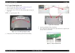
6.
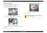
Remove the Print Head.
7.
Disconnect the Head FFC from the connector of the Print Head.
A D J U S T M E N T
R E Q U I R E D
Once you have replaced the Print Head with a new one, make the
following adjustments:
(Refer to
“Adjustment by Adjustment Program” on page 59
When you have removed once and then installed the Print Head,
make the following adjustments:
C H E C K
P O I N T
Installing the Print Head
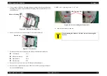
1.
Set the Head FFC in the holding portion (at C) of the Carriage
Unit. (See
Figure 4-20, "Removing the FFC Holder", p. 46
)
2.
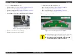
Make sure that the head grounding plate is installed on the
Carriage Unit properly.
Figure 4-22. Head Mounting Position
3.
Install the Print Head so that the two holes are put properly on
the respective pins of the Carriage Unit. (See
"Head Mounting Position", p. 47
4.
Secure the Print Head with the one screw (C.B.P-Tite SCREW
3x8 F/Zn) and one screw (C.B.B.-Tite W2 2.5x5 F/Zb).
Screw tightening torque;
C.B.P-Tite 3x8 F/Zn:0.5-0.7Nm
C.B.B-Tite W2 2.5x5 F/Zb:0.15-0.25Nm
Head positioning pin
Head grounding plate
Summary of Contents for Stylus CX3100
Page 1: ...EPSON StylusCX3100 3200 Scanner Printer Copier SERVICE MANUAL SEOT02002 ...
Page 5: ...Revision Status Revision Issued Date Description A Augusut 1 2002 First Release ...
Page 8: ...C H A P T E R 1 PRODUCTDESCRIPTION ...
Page 13: ...C H A P T E R 2 OPERATINGPRINCIPLES ...
Page 17: ...C H A P T E R 3 TROUBLESHOOTING ...
Page 34: ...C H A P T E R 4 DISASSEMBLYANDASSEMBLY ...
Page 57: ...C H A P T E R 5 ADJUSTMENT ...
Page 74: ...C H A P T E R 6 MAINTENANCE ...
Page 80: ...C H A P T E R 7 APPENDIX ...
Page 84: ......
Page 85: ......
Page 86: ......
Page 87: ......
Page 88: ......
Page 89: ...EPSON Stylus CX3100 3200 Revision A Appendix Exploded Diagrams 88 7 4 Exploded Diagrams ...
Page 90: ...EPSON Stylus CX3100 3200 Revision A Appendix ASP List 89 7 5 ASP List ...

