background image

2.1.1.1 Carriage Motor Driver Circuit

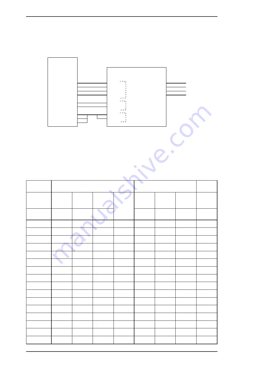
Carriage motor driver IC UDN2917EB (IC8) outputs a constant current to drive the carriage motor.
CPU M3772152BFP (IC2) determines the motor phase and speed, and then sends a signal to the
UDN2917EB carriage motor driver IC (IC8) via a 4-bit signal transmission line. The carriage motor is
controlled by a 2W1-2 phase drive method. The figure below shows the carriage motor driver circuit
block.

Motor driver IC UDN2917EB controls the motor stepping direction and drive current with a
combination of six signals supplied from the CPU. PH1 and PH2 signals control the current flow
direction to determine the motor stepping position; and the I10, I11 and I20, I21 signals determine the
drive current supplied to each motor drive coil. Table 2-1 lists the combinations of these signals used
for the 2W1-2 phase drive control.

Table 2-1. Carriage Motor Drive Sequences

Sequence

Phase A

Phase B

+

^

RTP03

RTP10

RTP11

Current

Duty

RTP02

RTP12

RTP13

Current

Duty

^

PH1

I11

I10

PH2

I21

I22

^

0

0

0

0

–1

0

1

1

0

1

0

0

0

–1

0

1

0

–1/3

2

0

0

1

–2/3

0

0

1

–2/3

3

0

1

0

–1/3

0

0

0

–1

4

1

1

1

0

0

0

0

–1

5

1

1

0

+1/3

0

0

0

–1

6

1

0

1

+2/3

0

0

1

–2/3

7

1

0

0

+1

0

1

0

–1/3

8

1

0

0

+1

0

1

1

0

9

1

0

0

+1

1

1

0

+1/3

10

1

0

1

+2/3

1

0

1

+2/3

11

1

1

0

+1/3

1

0

0

+1

12

0

1

1

0

1

0

0

+1

13

0

1

0

–1/3

1

0

0

+1

14

0

0

1

–2/3

1

0

1

+2/3

15

0

0

0

–1

1

1

0

+1/3

IC2
M37721S2BFP

RTP10
RTP11
RTP12
RTP13

RTP03
RTP02

P105
P106
P107

IC8
UDN2917EB

4
3
2
1

5

6

19
18
17

I10
I11
I20
I21

PH1
PH2

VREF1
VREF2

2
1

23
24

43
26

44
25

A

-A

B

-B

6
3

18
21

CRA
CR-A
CRB
CR-B

Drive current level

Stepping direction

Trip current level

Figure 2-2. Carriage Motor Drive Circuit Block Diagram

Operating Principles

EPSON Stylus COLOR 200 / EPSON Stylus 200

2-2

Rev. A

Summary of Contents for Stylus Color 200

Page 1: ...EPSON TERMINAL PRINTER EPSON Stylus Color 200 EPSON Stylus 200 SERVICE MANUAL EPSON Rev A 4006645 ...

Page 2: ...manual However should any errors be detected SEIKO EPSON would greatly appreciate being informed of them The above notwithstanding SEIKO EPSON can assume no resoinsibility for any errors in this manual or the consequence thereof Epson and Epson s ESC P are registered trademark of Seiko Epson Corporation General Notice Other product names used herein are for identication purpose only and may be tra...

Page 3: ...OT CONNECT THE UNIT TO A POWER SOURCE UNTIL INSTRUCTED TO DO SO WHEN THE POWER SUPPLY CABLE MUST BE CONNECTED USE EXTREME CAUTION IN WORKING ON POWER SUPPLY AND OTHER ELECTRONIC COMPONENTS WARNING 1 REPAIRS ON EPSON PRODUCT SHOULD BE PERFORMED ONLY BY AN EPSON CERTIFIED REPAIR TECHNICIAN 2 MAKE CERTAIN THATTHE SOURCE VOLTAGES IS THE SAME AS THE RATED VOLTAGE LISTED ON THE SERIAL NUMBER RATING PLAT...

Page 4: ... main components of the printer CHAPTER 2 OPERATING PRINCIPLES Describes the theory of printer operation CHAPTER 3 DISASSEMBLY AND ASSEMBLY Includes the step by step guide for product disassembly and assembly CHAPTER 4 ADJUSTMENTS Includes a step by step guide for adjustment CHAPTER 5 TROUBLESHOOTING Provides Epson approved techniques for adjustment CHAPTER 6 MAINTENANCE Describes preventive maint...

Page 5: ...REVISION SHEET Revision Issue Date Contents Rev A July 15 1996 1st issue v ...

Page 6: ...TABLE OF CONTENTS CHAPTER 1 PRODUCT DESCRIPTION CHAPTER 2 OPERATION PRINCIPLES CHAPTER 3 DISASSEMBLY AND ASSEMBLY CHAPTER 4 ADJUSTMENT CHAPTER 5 TROUBLESHOOTING CHAPTER 6 MAINTENANCE APPENDIX vi ...

Page 7: ...nterface Specifications 1 9 1 3 2 Parallel Interface Reverse channel 1 11 1 4 OPERATIONS 1 12 1 4 1 Control Panel 1 12 1 4 2 Panel Operation and Built in Function 1 12 1 4 3 Default Settings 1 14 1 4 3 1 Default Settings Items 1 14 1 4 3 2 Changing the Default Settings 1 15 1 4 4 Error Conditions 1 16 1 4 5 Printer Initialization 1 16 1 4 5 1 Power On Initialization 1 16 1 4 5 2 Sofware Initializa...

Page 8: ...eed and Printable Columns 1 2 Table 1 2 Character Tables 1 3 Table 1 3 Paper Specifications 1 4 Table 1 4 Adjust Lever Settings 1 5 Table 1 5 Paper Select Lever Settings 1 5 Table 1 6 Black I C Specifications 1 6 Table 1 7 Color I C Specifications 1 6 Table 1 8 Rated Electrical Ranges 1 7 Table 1 9 Acceptable Environmental Conditions 1 7 Table 1 10 Siganal and Connector Pin Assignment for Parallel...

Page 9: ... on special coated paper Use the monochrome head only with plain paper High speed print 10CPI Monochrome head 125cps LQ 167cps HS CMY head 200cps LQ one pass printing Note The CMY head prints 360 dpi printing in three passes Built in auto sheet feeder Cut sheets Transparency films A4 and letter Envelopes 10 sheets Plain papers 100 sheets 64g m2 Built in I F Parallel I F only 8 bit parallel IEEE P1...

Page 10: ...ing Table 1 1 Print Speed and Printable Columns Character Pitch Printable Columns Printing Speed cps Monochrome Normal Monochrome Draft CMY 10 cpi Pica 80 125 167 200 12 cpi Elite 96 150 200 240 15 cpi 120 188 250 300 17 cpi Pica condensed 136 214 285 342 20 cpi Elite condensed 160 250 333 400 1 1 1 2 2 2 19 20 19 20 20 19 1 2 3 4 5 6 64 61 59 62 63 60 Row M Row C Row Y A B C D E F 120 dpi 360 dpi...

Page 11: ...852 East Europe PC853 Turkish PC855 Cyrillic PC857 Turkish PC866 Russian PC869 Greek MAZOWIA Poland Code MJK Czecho Slovakia ISO 8859 7 Latin Greek ISO Latin 1T Turkish Bulgaria Bulgaria Fonts Bitmap LQ fonts EPSON Roman 10 cpi 12 cpi 15 cpi Proportional EPSON Sans Serif 10 12 15 Proportional EPSON Courier 10 12 15 Scalable fonts EPSON Roman 10 5 points 8 32 points in units of 2 points EPSON Sans ...

Page 12: ... Sheets Envelopes Transparencies A4 Letter Legal No 10 DL PW Width 210 mm 216 mm 216 mm 240 mm 220 mm PL Length 297 mm 279 mm 358 mm 104 mm 110 mm LM Left margin 3 mm or more 3 mm or more 3 mm or more 3 mm or more 3 mm or more RM Right margin 3 mm or more 3 mm or more 10 mm or more 33 8 mm or more 13 8 mm or more TM Top margin 3 mm or more 3 mm or more 3 mm or more 3 mm or more 3 mm or more BM Bot...

Page 13: ...r the paper varieties shown in Table 1 5 Table 1 5 Paper Select Lever Settings Specifications for the Medium PF Mode Cut Sheets Envelopes Postcards Lever Position ASF Feed Thick paper Rear NO OK Thinner paper Front OK NO Manual Feed Thick paper Rear OK OK Thinner paper Front NO NO Note OK means paper can be used and NO means paper cannot Paper In Paper Out Manual Feed Auto Feed Hopper Paper Select...

Page 14: ... Transit 120 hours or less at 60 C 140 F Dimensions 30 0 W 58 0 D 38 5 0 3 H mm Table 1 7 Color I C Specifications Item Specifications Type Exclusive cartridge Color and Weight Cyan Magenta Yellow Approximately 75 g internal ink weight is 12 8 g 0 5 g Ink Life 100 solid pattern A4 16 sheets each color Validity 2 years sealed in package 6 months out of package Storage Temperature 30 to 40 C 22 104 ...

Page 15: ...gth 1000 VAC rms for 1 minute or 1200 VAC rms for 1 second between AC line and chassis 1500 VAC rms for 1 minute between AC line and chassis 1 2 6 Environmental Conditions Table 1 9 Acceptable Environmental Conditions Condition Operating Non Operating Temperature 10 35 C 50 95 F 1 20 60 C 4 122 F 2 Humidity 20 80 RH 1 3 5 85 RH 2 3 Shock resistance 1G within 1 msec 2G within 2 msec 2 Vibration res...

Page 16: ...version EN 60950 TÜV SEMKO DEMKO NEMKO SETI Radio frequency interference RFI 120 V version FCC Part 15 Subpart B Class B 220 240 V version Vfg 243 VDE0878 part 3 part 30 EN55022 CISPR PUB 22 class B CSA C108 8 1 2 9 Acoustic Noise Level Approximately 45 dB A Per ISO 7779 1 2 10 Physical Specifications Dimensions W D H 396 7 mm W 205 6 mm D 149 0 mm H Weight About 3 9 kg 8 6 lb excluding head and i...

Page 17: ...phenol or equivalent Data transmission timing See Figure 1 6 Note Transition time rise time and fall time of every input signal must be less than 0 2 µs Parameter Minimum Maximum tsetup 500 nsec thold 500 nsec tstb 500 nsec tready 0 tbusy 500 nsec treply tack 500 nsec 10 us tnbusy 0 tnext 0 ttout 120 nsec ttin 200 nsec Rise and fall time of output siganls Rise and fall time of input signals data b...

Page 18: ...RROR O This signal s low level means the printer is in a state of error 35 5 V Pulled up to 5 V through 1 0 KΩ resistor in the printer 36 SLIN In Not used 17 CHASSIS Chassis ground 18 Logic H O Pulled up to 5V through 3 9 KΩ resistor 16 33 19 30 GND Signal ground 15 34 NC Not connected The I O column indicates the direction of the signal as viewed from the printer The busy signal is active HIGH un...

Page 19: ...Assignment for Reverse channel Pin No Signal Name I O Description 1 HostClk I Host clock signal 2 9 DATA 1 8 I Parallel Input data to the printer bit 0 LSB bit 7 MSB 10 PtrClk O Printer clock signal 11 PtrBusy DataBit 3 7 O Printer busy signal and reverse channel transfer data bit 3or7 12 AckDataReq DataBit 2 6 O Acknowledge data request signal and reverse channel transfer data bit 2 or 6 13 Xflag...

Page 20: ... can activate the following modes by doing the procedure in table 1 11 and 1 12 Table 1 12 Panel Operation Button Operations Single Button Operations Pressed and released Held down 3 seconds Cleaning Cleaning head No Function Load Eject Load Eject Exits from Ink Cartrige changing mode Enters to Ink Cartrige changing mode Power Load Eject Inkout Paperout Cleaning Light Button Figure1 7 Control Pane...

Page 21: ...ing Load Eject Cleaning Hold down both buttons over 10 seconds until Ink Out and Paper Out light blink Clear user setting on EEPROM Other combinations Other combinations Not available Table 1 14 Button Operations in Default Setting Mode Button Function Load Eject Move through each menu Cleaning Select Table 1 15 Error Indications Printer Status Indicators Power Inkout Paperout Ink low printable On...

Page 22: ...rk Italic Sweden Italic Italy Italic Spain PC437 PC850 PC860 PC863 PC865 PC861 BRASCII Abicomp NLSP Version Italic USA Italic France Italic Germany Italic UK Italic Denmark Italic Sweden Italic Italy Italic Spain PC437 PC850 PC853 PC857 PC437 Greek PC855 PC866 PC852 PC869 ISO 8859 7 ISO Latin 1T MAZOWIA Code MJK Bulgaria Typestyles Roman Sans Serif Courier Roman T PS Sans Serif H PS Character Pitc...

Page 23: ...ect the language used to print messages 2 Power InkOut and PaperOut LED indicate the top item English on Language Menu You can select a language by pressing the Cleaning button See Table 1 16 Table 1 18 Language Selection Power InkOut PaperOut English On Off Off Français Off On Off Deutsch On On Off Italiano Off Off On Español On Off On 3 Press Load Eject button the setting sheet is printed out in...

Page 24: ...ecute Operator initialization 1 4 5 2 Software Initialization This initialization of this level is activated by the control code ESC This initialization is to clear the unprinted data to make the printer s setting defaults 1 4 5 3 Operator Initialization The initialization of this level is activated by INIT signal negative pulse reset operation through panel or head replacement between monchrome a...

Page 25: ...ntrol board C199 MAIN Board consists of an M37721S2BP 16 bit CPU The E05B32 gate array operates with 25MHz clock speed and controls various memories The CR motor and PF motor are controlled directly by the CPU CN1 CN2 CN3 CN4 CN5 CN6 CN7 CN8 SW3 SW2 SW1 CPU M3772051 IC2 E05B08 IC1 4M or 8M Bit PROM IC3 1M Bit PSRAM IC4 8M Bit CG ROM IC5 Figure 1 8 C199 Main Control Board Component Layout Epson Sty...

Page 26: ...operate in order to perform the head capping operation 1 5 3 Interface Board C160 I F Board There is an exclusive interface board to receive transmit print data between the host computer and printer Trans T1 C11 Q1 FET CN2 CN1 Fuse F1 Choke Cil C1 Photo Coupler PC1 Photo Coupler PC2 Power SW Filter L1 Figure 1 9 C160 PSB PSE Board Component CN1 CN2 JAPAN version only Serial I F Figure1 10 C160 I F...

Page 27: ... Housing The Epson Stylus Color 200 Epson Stylus 200 housing consists of the printer cover upper case and lower case Attached to the housing are the front paper support and ejected paper support with paper separator Upper Case Eject Paper Stacker M4C10 Mechanism Space Waste Ink Drain Tank Figure 1 12 Housing Component Layout Figure 1 11 M 4C11 Printer Mechanism Epson Stylus Color 200 Epson Stylus ...

Page 28: ... 2 1 2 1 1 1 Carriage Motor Driver Circuit 2 2 List of Figures Figure 2 1 C199 Main Board 2 1 Figure 2 2 Carriage Motor Drive Circuit Block Diagram 2 2 List of Tables Table 2 1 Carriage Motor Drive Sequence 2 2 Table 2 2 Connection between the reference and the output signal 2 3 Rev A 2 i ...

Page 29: ...oard used in the EPSON Stylus COLOR IIs is that the new board incorporates a new CR drive circuit The figure below shows a block diagram of the C199 MAIN board circuitry CPU M37721S2BFP IC2 G A E05B32KB IC1 PROM 2 8M IC3 PSRAM 1M IC4 PSRAM 256K IC5 MROM 16M IC6 MROM 16M IC7 UDN2917EB IC8 A2919 IC16 CR motor driver PF motor driver Panel switch Panel LED EEPROM IC10 Address Data Bus Address Bus Data...

Page 30: ...coil Table 2 1 lists the combinations of these signals used for the 2W1 2 phase drive control Table 2 1 Carriage Motor Drive Sequences Sequence Phase A Phase B RTP03 RTP10 RTP11 Current Duty RTP02 RTP12 RTP13 Current Duty PH1 I11 I10 PH2 I21 I22 0 0 0 0 1 0 1 1 0 1 0 0 0 1 0 1 0 1 3 2 0 0 1 2 3 0 0 1 2 3 3 0 1 0 1 3 0 0 0 1 4 1 1 1 0 0 0 0 1 5 1 1 0 1 3 0 0 0 1 6 1 0 1 2 3 0 0 1 2 3 7 1 0 0 1 0 1 ...

Page 31: ...nt control Table 2 2 lists the connection of the output signals and the reference trip current levels Table 2 2 Connection between References and Output Signals Reference Trip Current P105 P106 P107 Duty Change 601 mA OFF OFF OFF 1 2 3 1 3 0 481 mA ON OFF OFF As above 444 mA OFF ON OFF As above 403 mA OFF OFF ON As above 375 mA ON ON OFF As above 345 mA ON OFF ON As above 326 mA OFF ON ON As above...

Page 32: ... Removal 3 5 3 2 5 M 4C11 Printer Mechanism Removal 3 6 3 2 6 Printer Mechanism Disassembly 3 7 3 2 6 1 Carriage Unit Removal 3 7 3 2 6 2 ASF Unit Removal 3 9 3 2 6 3 PE Sensor Removal 3 9 3 2 6 4 Pick Up Roller Unit Removal 3 10 3 2 6 5 Carriage Home Position Sensor Removal 3 10 3 2 6 6 Paper Feed Roller Unit Removal 3 11 3 2 6 7 Carriage Motor Removal 3 11 3 2 6 8 Head Cleaner Replacement 3 12 3...

Page 33: ...val 3 7 Figure 3 9 Parallelism Adjust Lever Removal 3 8 Figure 3 10 Carriage Unit Removal 3 8 Figure 3 11 ASF Unit Removal 3 9 Figure 3 12 PE Sensor Removal 3 9 Figure 3 13 Pick Up Roller Unit Removal 3 10 Figure 3 14 Carriage Home Position Sensor 3 10 Figure 3 15 Paper Feed Roller Unit Removal 3 11 Figure 3 16 Carriage Motor Removal 3 11 Figure 3 17 Head Cleaner Replacement 3 12 Figure 3 18 Pump ...

Page 34: ...act with your skin wash it off with soap and water If irritation occurs contact a physician Never remove the ink cartridge from the carriage unless manual instructions specify to do so When transporting the printer after installing the ink cartridge be sure to pack the printer for transportation without removing the ink cartridge Use only recommended tools for disassembling assembling or adjusting...

Page 35: ...M4X11 CBB M4X11 CBB M4X11 CBB M4X11 Small Screw Figure 3 1 Upper Case Removal START 3 2 1 Page 3 2 Upper Case Removal 3 2 2 Page 3 3 C199 Main Board Removal 3 2 3 Page 3 4 C160 I F Board Removal 3 2 4 Page 3 5 C160 PS Board Removal 3 2 5 Page 3 6 M 4C11 Mechanism Removal 3 2 6 1 Page 3 7 Carriage Unit Removal 3 2 6 2 Page 3 9 ASF Unit Removal 3 2 6 3 Page 3 9 PE Sensor Removal 3 2 6 4 Page 3 10 Pi...

Page 36: ...the C199 Main Control Board 4 Remove a CBB M3x6 screw fixing a ASF Sensor holder to printer mechanism When you replace the C199 MAIN Board reset the EEPROM and perform the required adjustments See Chapter 4 CBB M3x6 C160 PSB PSE Board ASF Sensor Holder Figure 3 3 ASF Sensor Removal CBB M3x6 CBB M3x6 CBB M3x6 CBB M3x6 Shield Plate CN1 CN8 CN7 CN4 CN3 CN5 CN6 C199 Main Board CN9 Figure 3 2 C199 Main...

Page 37: ...ove the board frame 3 2 3 C160 I F Board Removal 1 Remove the upper case see Section 3 2 1 2 Remove 2 CPS M3 6 screws and 1 CBB M3 10 securing the C160 I F Board to the mechanism and bottom case 3 Disconnect CN1 on this board then remove it by lifting it up 1 0 Transpearency plate CPS M3x6 CPS M3x6 Board Frame Metal stay CPS M3x6 Figure 3 4 Board Frame and Metal Stay Removal CBB M3x10 CPS M3x10 CP...

Page 38: ...screw securing the board frame to the grounding plate 1 CBB M3x10 screw fixing the board frame and 1 big screw securing the board frame to the lower case via the grounding plate CPS M3x6 CBB M3x10 Big Screw CBB M3x10 C160 PSB PSE Board Grounding Plate Figure 3 6 C160 PSB PSE Board Removal EPSON Stylus Color 200 EPSON Stylus 200 Disassembly and Assembly Rev A 3 5 ...

Page 39: ...C160 power supply board see Section 3 2 4 5 Remove 4 CBB M4x11 screws securing the printer mechanism to the lower case When you replace the printer mechanism perform the required adjustments See Chapter 4 CBB M3x11 CBB M3x11 CBB M3x11 CBB M3x11 M 4C11 Printer Mechanism Figure 3 7 Printer Mechanism Removal CAUTION Disassembly and Assembly EPSON Stylus Color 200 EPSON Stylus 200 3 6 Rev A ...

Page 40: ... Remove the printer mechanism see Section 3 2 6 2 Remove the blue PG lever 3 Remove the tension coil securing the parallelism bushing to the side frame Use only O 11 oil when lubricating the carriage guide shaft 1 1 2 0 PG Lever Tension Spring Figure 3 8 PG Lever and Tension Coil Removal CAUTION EPSON Stylus Color 200 EPSON Stylus 200 Disassembly and Assembly Rev A 3 7 ...

Page 41: ...g belt while pressing the pulley holder then remove the carriage unit along with the carriage guide shaft Parallelism Adjust Lever Lever Knob 1 2 Figure 3 9 Parallelism Adjust Lever Removal 1 Pulley Holder Figure 3 10 Carriage Unit Removal Disassembly and Assembly EPSON Stylus Color 200 EPSON Stylus 200 3 8 Rev A ...

Page 42: ...op of the ASF unit toward the front of the mechanism to clear the PE sensor 3 2 6 3 PE Sensor Removal 1 Remove the printer mechanism see Section 3 2 5 2 Remove the ASF unit see Section 3 2 6 2 3 Disconnect CN7 on the C199 MAIN Board then remove the PE sensor 2 1 1 ASF Unit CAUTION ASF Unit PE Sensor Actuator Figure 3 11 ASF Unit Removal PE Sensor Actuator 1 Screw Figure 3 12 PE Sensor Remopval CAU...

Page 43: ...lustration 3 2 6 5 Carriage Home Position Sensor Removal 1 Remove the printer mechanism see Section 3 2 5 2 Disconnect the CN8 on the C199 MAIN Board 3 Remove the 2 CPS M3x6 screws securing the metal stay to the printer mechanism 0 1 2 Pick Up Roller Unit Shaft Holder Washer Tension Spring Figure 3 13 Pick Up Roller Unit Removal CPS M3x6 Carriage Home Position Sensor Carriage Motor Figure 3 14 Car...

Page 44: ...emove the printer mechanism see Section 3 2 5 2 Remove the carriage unit see Section 3 2 6 1 3 Remove the carriage CR motor Note When you remove the CR motor be sure to keep the washer on the CR motor gear When you remove or remount the CR motor be careful of the post at both the top and bottom of the motor If this post is broken the motor will not seat correctly and can move during printing Paper...

Page 45: ...6 6 3 Use tweezers to unhook the head cleaner Never touch the head cleaner with your bare hands When attaching the head cleaner wear gloves and use clean tweezers to handle it 0 1 Head Cleaner Hook Platen Figure 3 17 Head Cleaner Replacement CAUTION Disassembly and Assembly EPSON Stylus Color 200 EPSON Stylus 200 3 12 Rev A ...

Page 46: ...ws 1 CPS M3x6 1 CPS M3x12 and 1 CPS M3x8 securing the pump unit to the main frame 7 Release a tension spring securing the paper pick up trigger holder to the pump mechanism Notes 1 When you remove the pump unit be sure to keep the washer located behind the pump 2 When you remove the pump unit do not lose the pin in the pin holder White Tube CPS M3x6 Figure 3 18 Pump Unit Removal 1 CPS M3x6 CPS M3x...

Page 47: ...e Section 3 2 6 9 3 Remove the 2 CBB M3x10 screws securing the paper feed motor to the motor frame Pin HOLE Pin Holder Pump Unit Pin Figure 3 20 Pin Position PF Motor CBB M3x10 CBB M3x10 Pump Unit Figure 3 21 Paper Feed Motor Removal Disassembly and Assembly EPSON Stylus Color 200 EPSON Stylus 200 3 14 Rev A ...

Page 48: ...djustment 4 3 4 1 4 Platen Gap Adjustment 4 4 4 1 5 EEPROM Reset Procedure 4 5 List of Figures Figure 4 1 Bi D Alignment 4 2 Figure 4 2 Angle Lever Operation 4 3 Figure 4 3 PG Lever Operation 4 4 Figure 4 4 Confirmation Method 4 7 List of Tables Table 4 1 Required Adjustments 4 1 Table 4 2 Gap and Adjustment Direction 4 4 Table 4 3 EEPROM Operation 4 5 Rev A 4 i ...

Page 49: ...i D Alignment Adjustment see 4 1 1 After replacing the C199 MAIN board 1 EEPROM Reset see 4 1 5 2 Bi D Alignment Adjustment see 4 1 1 When vertical lines are not aligned When a white line appears after the printer performs a single print pass 1 Bi D Alignment Adjustment see 4 1 1 2 Head Angle Adjustment see 4 1 2 After replacing or disassembling the carriage unit Platen Gap Adjustment see 4 1 4 Wh...

Page 50: ...ent is Necessary After replacing the C199 MAIN board After replacing the printer mechanism After disassembling the printer mechanism for example to replace the carriage motor After replacing the printhead Adjustment Procedure 1 Connect the printer to the PC and load paper in the printer 2 Run adjustment program CLR200 EXE on the PC Then follow the program instructions and select the Bi D alignment...

Page 51: ...ow change the position of the adjust lever on the carriage unit To move the reference line UPWARD Move the lever to the FRONT To move the reference line DOWNWARD Move the lever to the REAR 3 When the adjustment is complete return to the program s main menu and turn the printer off 4 1 3 Zig Zag Adjustment If a vertical line for example the vertical strokes of the character H is jagged adjust the d...

Page 52: ...p and Adjustment Direction Gap between Head Nose and Gauge Surface Move Left Bushing Move Right Bushing Too narrow Clockwise CW Counterclockwise CCW Too wide Counterclockwise CCW Clockwise CW 3 Rotate the parallelism adjustment bushing attached to the left and right ends of the carriage guide shaft until the black or color printhead contacts the thickness gauge 4 After placing the printheads again...

Page 53: ... a Maintenance Error Refer to 4 1 5 4 After replacing the printhead with a new one Refer to 4 1 5 3 Printer indicates a Maintenance Error Refer to 4 1 5 4 4 1 5 1 Writing Data to the EEPROM If the main board needs to be replaced even if it still works correctly you need to print out all the data stored in the current EEPROM and write and save the settings to the EEPROM on the new board This is par...

Page 54: ...ations or ink system malfunctions 1 Replace the ink cartridge or the printhead with a new one 2 Run adjustment program CLR200 EXE and select EEPROM Data Manipulation from the main menu 3 If you replaced the ink cartridge choose INK COUNTER CLEAR from the sub menu or if you replaced the printhead choose INITIAL CHARGE FLAG RESET 4 1 5 4 Maintenance Error Clear The ink system monitors the amount of ...

Page 55: ...g Construction 5 1 Figure 5 2 Main Flow Chart for Recover a Dot missing 5 8 Figure 5 3 360 DPI Check Pattern 5 9 Figure 5 4 Standard of Dot missing 5 9 Figure 5 5 The Bent part on the Cap Rubber 5 10 LIST OF TABLES Table 5 1 Motor Resistance 5 1 Table 5 2 Sensor Status 5 2 Table 5 3 Repair of the C160 PSB PSE 5 3 Table 5 4 Repair of the C199 Main 5 4 Table 5 5 Repair of the Printer Mechanism 5 6 T...

Page 56: ... they are very difficult to eliminate Refer to the Section 5 5 to attempt to clear clogged nozzle s The ink out sensor on the printer is monitored by the firmware counter If you replace an ink cartridge before its ink sensor is activated you must clear the EEPROM first Table 5 1 Motor Resistances Motor Resistance Range Temperature CR Motor 22 Ω 7 At 25 C 77 F PF Motor 21 Ω 1 Ω At 25 C 77 F START E...

Page 57: ... to Pin 8 GND L GND Cartridge exists H 5 V No cartridge M C Sensor CN4 Pin 19 M C to Pin 8 GND L GND Color cartridge exists H 5 V Black cartidge exists HP Sensor CN8 Pin 1 HP to Pin 2 GND L At home position HP H Out of HP ASF Sensor CN9 Pin 1 ASF to Pin 2 GND L Manual feed mode H Auto feed mode Troubleshooting Epson Stylus Color 200 Epson Stylus 200 5 2 Rev A ...

Page 58: ...s broken Check the wave form at the drain of Q1 Replace Q1 Q2 or Q3 is broken Check the wave form at the drain of Q2 and Q3 Replace Q2 or Q3 Check the wave form at 3 pin of PC1 Replace PC1 PC1 is broken 5V is dead L4962 is broken Check the oscillation at 5 pin of IC51 Replace IC51 Check the output wave form at 7 pin of IC51 Replace IC51 Sympton Condition Cause Checkpoints Solution Printer does not...

Page 59: ... IC2 is defective Does wave form of CRU1 is correct at either pin 37 and 38 of CPU Correct replace IC2 Incorrect replace CRU1 CRU2 or IC1 is defective Does wave form of CRU2 is correct Refer to above wave form Correct replace IC1 Incorrect replace CRU2 Gate array does not operate Check the wave form at the pin 52 54 56 57 58 Replace IC1 OE signal does not output Gate array does not operate Check t...

Page 60: ...AIN Cont Does the wave form correct Check pin at 17 20 and 14 23 Correct replace motor Incorrect repalce IC12 Drive pulse does not output PF motor does not operate normally CPU is defective IC16 is defective Does the wave form correct Check pin either at 3 and 4 Replace CPU Does the wave form correct Check pin at 17 20 and 14 23 Correct replace motor Incorrect repalce IC12 Epson Stylus Color 200 E...

Page 61: ... Replace the printhead to see if this causes the ink to be absorbed normally Replace the printhead The carriage motor does not rotate The carriage motor fails to rotate at power on PG value is incoorect Check the PG value 1 18 mm 1 100 Remove any foreign substances CRHP sensor is defective Check voltage reaction at pin 1 on CN8 Replace CRHP The carriage motor is defective Measure the coil resistan...

Page 62: ...sibility that Ink low or Ink out error indications might appear Therefore make sure to reset the EEPROM firmware counter after the ink cartridge is replaced Also the waste ink drain pad should be replaced according to its conditions Only when the printhead is installed for the first time indiviual dummy CL sequences for black and color head need to be done initial charge However once initial charg...

Page 63: ...fer to Section 5 5 1 3 Perforn the 360 DPI printing Refer to Section 5 5 1 1 Yes No A Replace to new ink cartridge Perform the initila ink charge with the program Perforn the 360 DPI printing Refer to Section 5 5 1 1 Printing is recovered Yes A No Refer to Section 5 5 1 5 Perform the initila ink charge with the program Refer to Section 4 1 3 Perforn the 360 DPI printing Refer to Section 5 5 1 1 Pr...

Page 64: ...rt the paper to the hopper and load a paper Step 3 Execute the adjustment program CLR200 EXE and select Print CHECK PATTERN The printer print the chekc pattern as shown below 5 5 1 2 Standard of Is the printing normal If the 360 DPI printing pattern has a following problem advance to next step on the flow chart Section 5 5 1 3 Figure 5 3 360 DPI Check Pattern White banding There is a projection pa...

Page 65: ...tep before going to the next step on the main flow chart Observing the cap from above make sure there are not any bents holes or scars on the surface Note If you can not find any problems about the pump unit system or the above contents there is a possibility that an ink in the ink cartridge has already emptied in spite of any counter values so that it is necessary to replace to the brand new ink ...

Page 66: ...stment program to perform the initial charge operation again on the same printer Step 1 Execute the adjustment program CLR200 EXE and select EEPROM Data Manipulation Step 2 Choose INITIAL CHARGE FLAG RESET from the sub menu Step 3 Install new printhead and new ink cartridge on the printer Then turn the printer on to start the initial charge operation 5 5 1 6 Replace to new ink cartridge It is nece...

Page 67: ... Cleaning 6 1 6 1 2 Waste Ink Drain Tank Replacement 6 2 6 1 3 Lubrication and Adhesives 6 3 LIST OF FIGURES Figure 6 1 Lubrication Points and Adhesive Points 6 4 LIST OF TABLES Table 6 1 Recommended Lubricants 6 3 Table 6 2 Lubrication Points 6 3 Table 6 3 Adhesive Points 6 3 Rev A 6 i ...

Page 68: ...h for cleaning Be careful not to damage the components of the printer when using a vacuum cleaner If ink gets into your eyes flush them immediately with clean water and ask for medical attention Disconnect the printer from the power source when you clean inside the printer Once removed ink cartridge must be replaced to the brand new cartridge when the printer is sent back to the user Regfer to the...

Page 69: ...three lights blink and indicate error status Maintenance request see Chapter 1 Error indications Table 1 15 When this error is displayed replace the waste ink drain pad and reset the protect counter 1 Remove the printer mechanism Refer to3 2 5 and replace the waste ink tank located in the waste ink tank 2 After reassemble the printer take following steps in order to reset the protect counter 3 Tur...

Page 70: ... available Table 6 2 Lubrication Points Ref No Lubrication Point Name Quantity 1 Oil pad on the carriage O 11 0 2 cc 2 Pick up roller hole on the Pump unit G 36 1 3 mg 3 Both sides of the platen unit G 36 1 3 mg 4 Pump transmission gear Black color G 36 1 3 mg 5 Clutch mechanism Between PF and pump G 36 1 3 mg 6 Left shaft on the paper feed roller unit G 36 1 3 mg 7 E ring on the paper feed roller...

Page 71: ...Figure 6 1 Lubrication and Adhesive Point Maintenance Epson Stylus Color 200 Epson Stylus 200 6 4 Rev A ...

Page 72: ...out A 9 Figure A 7 C199 MAIN Control Component Layout A 10 Figure A 8 EPSON Stylus Color 200 Exploded Diagram 1 A 11 Figure A 9 EPSON Stylus Color 200 Exploded Diagram 2 A 12 Figure A 10 Stylus Color IIs 820 Exploded Diagram 3 A 13 LIST OF TABLES Table A 1 Connector Summary A 2 Table A 2 Connector Pin Assignments CN1 A 2 Table A 3 Connector Pin Assignments CN2 A 3 Table A 4 Connector Pin Assignmen...

Page 73: ...mponents of the Epson Stylus Color 200 Epson Stylus 200 AC INLET C160PSB CN 1 CN2 CN6 CN1 CN7 P E CN9 ASF CN 8 H P C199MAIN CN4 CN5 CN3 Centronics PF MOTOR CR MOTOR CN2 SERIAL Head Figure A 1 Interconnection of Major Components Epson Stylus Color 200 Epson Stylus 200 Appendix Rev A A 1 ...

Page 74: ...Power Supply from C160 PS board CN7 2 PE Sensor CN8 3 Carriage Home Position Sensor CN9 2 ASF sensor C160 PSB PSE CN1 2 AC inlet L N CN2 8 DC output 5 V 35 V Table A 2 Connector Pin Assignments CN1 Pin I O Name Description 1 GND Ground 2 FG Frame Ground 3 LOGH Logic Hights 4 I AFXT Auto line feed signal 5 5V 5VDC 6 O SLCT Printer select signal 7 I SLIN Select in signal 8 PE Paper end 9 O ERR Error...

Page 75: ...rive phase B 4 O CR B Carriage motor drive phase B Table A 5 Connector Pin Assignments CN4 Pin I O Name Description 1 FG Frame ground 2 VDD 5VDC 3 I CO Cartridge In Out sensor 4 6 8 GND Ground 5 O HCLK Head clock signal 7 O LATCH Head latch signal 9 O SI Serial data signal 10 I ID4 Head ID signal 11 12 GND2 Ground for head control voltage 13 14 O COM Head voltage 15 I ID1 Head ID signal 16 I ID2 I...

Page 76: ... supply board 2 4 GND Ground 3 I 5VDC Logic voltage suupply from power supply board Table A 8 Connector Pin Assignments CN7 Pin I O Name Description 1 I PE Paper in out state detection signal 2 GND Ground Table A 9 Connector Pin Assignments CN8 Pin I O Name Description 1 I HP Home position detection signal 2 GND Ground 3 O HPV 5VDC Table A 10 Connector Pin Assignments CN9 Pin I O Name Description ...

Page 77: ...A 2 CIRCUIT DIAGRAM Figure A 2 C160 PSB Board Circuit Diagram Epson Stylus Color 200 Epson Stylus 200 Appendix Rev A A 5 ...

Page 78: ...Figure A 3 C160 PSE Board Circuit Diagram Appendix Epson Stylus Color 200 Epson Stylus 200 A 6 Rev A ...

Page 79: ...Figure A 5 C160 PSB Board Component Layout Figure A 6 C160 PSE Board Component Layout Epson Stylus Color 200 Epson Stylus 200 Appendix Rev A A 9 ...

Page 80: ...A 3 Circuit Board Component Layout Figure A 7 C199 Main Control Board Component Layout Appendix Epson Stylus Color 200 Epson Stylus 200 A 10 Rev A ...

Page 81: ...A 4 Exploded Diagram Figure A 8 EPSON Stylus Color 200 Exploded Diagram 1 Epson Stylus Color 200 Epson Stylus 200 Appendix Rev A A 11 ...

Page 82: ...Figure A 9 EPSON Stylus Color 200 Exploded Diagram 2 Appendix Epson Stylus Color 200 Epson Stylus 200 A 12 Rev A ...

Page 83: ...Figure A 10 EPSON Stylus Color 200 Exploded Diagram 3 Epson Stylus Color 200 Epson Stylus 200 Appendix Rev A A 13 ...

Page 84: ...EPSON ...

Reviews: