background image

SC-S30600 Series

Revision B

ADJUSTMENT

Other Printer Checks and Adjustments

274

Confidential

4.15.8  Motor Measurement & Automatic Adjustment

The measurement adjustment can be made for the following motors individually.

CR Motor

Pump Motor (Pump Cap Unit)

PF Motor

EXECUTION MODE

Normal Mode

PROCEDURE

1.

Turn the printer ON.

2.

Start the Service Program and select 

Motor Measurement & Automatic 

Adjustment

 of the target motor.

3.

Click 

[Run]

.

Measurement and adjustment are performed automatically.

4.

When finished, click 

[Finish]

.

5.

Turn the printer OFF to finish the adjustment.

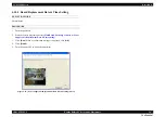
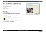
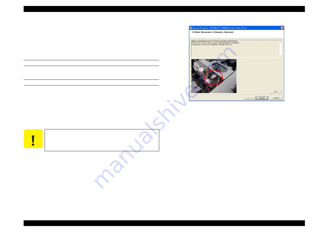
Figure 4-69.  [Motor Measurement & Automatic Adjustment] Screen

C A U T I O N

If the adjustment is not finished, replace the motor.

Summary of Contents for SC-S30600

Page 1: ...SC S30600Series Large Format Color Inkjet Printer SERVICE MANUAL SEIJ11002 Confidential ...

Page 2: ... of this manual However should any errors be detected SEIKO EPSON would greatly appreciate being informed of them The above not withstanding SEIKO EPSON CORPORATION can assume no responsibility for any errors in this manual or the consequences thereof EPSON is a registered trademark of SEIKO EPSON CORPORATION General Notice Other product names used herein are for identification purpose only and ma...

Page 3: ...EMBLING OR ASSEMBLING A PRODUCT MAKE SURE TO WEAR GLOVES TO AVOID INJURY FROM METAL PARTS WITH SHARP EDGES WARNING 1 REPAIRS ON EPSON PRODUCT SHOULD BE PERFORMED ONLY BY AN EPSON CERTIFIED REPAIR TECHNICIAN 2 MAKE CERTAIN THAT THE SOURCE VOLTAGES IS THE SAME AS THE RATED VOLTAGE LISTED ON THE SERIAL NUMBER RATING PLATE IF THE EPSON PRODUCT HAS A PRIMARY AC RATING DIFFERENT FROM AVAILABLE POWER SOU...

Page 4: ...PRODUCT DESCRIPTIONS Provides a general overview and specifications of the product CHAPTER 2 TROUBLESHOOTING Describes the step by step procedures for the troubleshooting CHAPTER 3 DISASSEMBLY ASSEMBLY Describes the step by step procedures for disassembling and assembling the product CHAPTER 4 ADJUSTMENT Provides Epson approved methods for adjustment CHAPTER 5 MAINTENANCE Provides preventive maint...

Page 5: ...f equipment May indicate an operating or maintenance procedure practice or condition that is necessary to accomplish a task efficiently It may also provide additional information that is related to a specific subject or comment on the results achieved through a previous action Indicates an operating or maintenance procedure practice or condition that if not strictly observed could result in injury...

Page 6: ...ally revised Chapter 3 3 4 1 1 Unlocking the CR Unit p 82 Contents of CAUTION were modified 3 4 6 9 PE Sensor p 170 REASSEMBLY was added Chapter 4 4 1 2 Adjustment Items and the Order by Repaired Part p 200 partially revised 4 10 7 Auto Bi D Adjustment p 242 revised Chapter 5 5 4 Exchange Parts p 280 revised 5 6 Lubrication p 288 revised Chapter 6 6 3 Panel Menu Map p 307 revised ...

Page 7: ... 59 2 8 Trouble on NVRAM Viewer 60 Chapter 3 DISASSEMBLY ASSEMBLY 3 1 Overview 62 3 1 1 Precautions 62 3 1 2 Cautions After Assembling 64 3 1 3 Orientation Definition 64 3 1 4 Recommended Tools 65 3 2 Parts Diagram 66 3 3 Disassembly Flowchart 76 3 4 Disassembly and Assembly Procedure 82 3 4 1 Preparation for Servicing 82 3 4 2 Consumables Accessories 84 3 4 3 Housing 86 3 4 4 Electric Circuit Com...

Page 8: ...ut 264 4 14 2 MAC Address Input 265 4 14 3 Serial Number Input 266 4 14 4 Board Replacement Date Time Setting 267 4 15 Other Printer Checks and Adjustments 268 4 15 1 USB Port and Network Communication Check 268 4 15 2 Suction Fan Adjustment 269 4 15 3 Heater Function Check 270 4 15 4 Panel Setting Reset Job History Reset 271 4 15 5 Single Channel Cleaning 272 4 15 6 Panel LCD Operation Check 273 ...

Page 9: ...Confidential C H A P T E R 1 PRODUCTDESCRIPTION ...

Page 10: ...ance Simplifies the maintenance by setting the routine maintenance operations into the shortcut keys on the control panel Media handling Spindleless Simplifies the setting of roll paper by assembling the lift levers Supports high capacity roll paper up to 80 kg by using optional heavy roll media system Settings before printing Automatizes Bi d Adjustment and Gap Adjustment by the IM Sensor Nightti...

Page 11: ...DESCRIPTION Product Description 11 Confidential Improvement of reliability durability Head life 1 5 year or 6 840 billion shots 1 line Operating life of the printer 5 years or 67 500 m2 64 inches 720x720 dpi Bi d Figure 1 1 External View ...

Page 12: ... operation environment 20 to 80 recommended range 40 to 60 Non condensing When storing 5 to 85 Non condensing Row A Row B Row C Row D Row E Row F Row G Row H Row I Row J C M Y PK PK Y M C Printer Heater Additional Dryer Rated voltage 100 to 240 VAC 100 to 240 VAC 100 to 240 VAC Rated frequency 50 to 60 Hz 50 to 60 Hz 50 to 60 Hz Rated current 10A 5A 10A 5A 1A 0 5A Power consumption Operating Appro...

Page 13: ...llow Magenta Cyan Cartridge life See the date printed on the package at normal temperature Guaranteed life after installation 6 months after mounted in the printer Storage Uninstalled packed 20 to 40 C within 1 month under 40 C Installed 10 to 40 C within 1 month under 40 C Transporting packed 20 to 60 C within 1 month under 40 C and within 72 hours under 60 C Capacity 700 ml Dimensions 40 W x 305...

Page 14: ...cannot be fed Application Type Signage Adhesive vinyl chloride film Vinyl chloride banner Fine art Canvas Window graphics PET Indoor POP Poster Glossy paper Matte paper Soft signage Polyester C H E C K P O I N T Recommended Media Settings Media settings can be adjusted from the printer control panel using the Custom Settings menu Note Selecting 2 0 for Platen Gap may disable auto Head Alignment He...

Page 15: ... Side Margin Left over 10 mm when using media holding plates 2 The total of the values selected for Print Start Position and Side Margin Right in the setup menu The default value is 5mm Chose a Print Start Position or Side Margin Right over 10 mm when using media holding plates Figure 1 2 Printable area OTHERS Borderless printing Not supported Paper board Not supported Designated paper Not support...

Page 16: ... Dimensions WEIGHT 1 4 2 Installation Room Requirement Figure 1 4 Installation Room Requirement Description Width Depth Height Standard 2 620 mm 963 mm 1 311 mm Maximum Tensioner Lift Lever and Media Loading Lever are extended 2 620 mm 1 259 mm 1 650 mm Depth Height Width Item Weight Main body 146 kg Standard Roll Unit 19 5 kg Standard Reel Unit 21 5 kg Legs 32 kg Optional Roll Unit 18 5 kg Option...

Page 17: ...nk Cartridge Lock Lever Cartridge Check Lamp Media Loading Lever Alert Lamp Maintenance Cover Right LAN Port Tensioner Paper Core Holder Locking Screw Roll Support Auto Switch Manual Switch Caster Airflow Vents Waste Ink Bottle Waste Ink Bottle Holder Adjust Waste Ink Tube AC Inlet USB Port Roll Core Holder CR Unit Print Head Cutter Groove Cap Platen Heater Wiper Media Holding Plate Flushing Pad W...

Page 18: ...0600 Series Revision B PRODUCT DESCRIPTION Hardware Specifications 18 Confidential BACK SIDE Figure 1 7 Back Side Drive Switch Roll Supporter Roll Holder Fixing Screw Lift Lever Pre Heater Handle Roll Holder ...

Page 19: ...ring character position when registering the setting name or setting IP address in the Setup Menu 8 Media Feed buttons Advances rewinds the media Hold down button to advance the media up to 3 m Hold down button to rewind the media up to 20 cm Selects the menu or the set value while the Setup Menu is displayed 9 OK button Determines the items or the settings 10 Heating and Drying button Sets the te...

Page 20: ...ure The heater temperature has not reached the preset temperature 1 2 3 4 5 6 3 Media information The setting number of the selected media platen gap media width and remaining amount of the media are indicated from the left Icons of platen gap change according to the set value as follows 1 5 2 0 2 5 4 Ink cartridge status The current ink level and status are indicated Ready Low Under the limit amo...

Page 21: ...0600 Series Revision B PRODUCT DESCRIPTION Control Panel 21 Confidential 6 Additional dryer status The setting of additional dryer is displayed Drying fan functions Drying fan does not function Name Function ...

Page 22: ...the media setting in one of the numbers set it in Customize Settings 1 to 30 Media Setup Numbers Customize Settings Current Settings Changes the current media setting The items which can be changed depend on which setting is selected RIP Settings or media number For the items refer to RIP Settings or the row of 1 to 30 as follows RIP Settings Platen Gap 1 5 Changes the Platen Gap gap between the P...

Page 23: ...note that print times will increase Every Page Off Media Tension 0 to 40 Increase tension if creases appear in media during printing The higher the value the greater the tension 1 to 30 Media setting bank Setting Name Names to the storing media setting within 18 characters of the one byte alphabet and numbers Giving a name for easy identification is recommended Feed Adjustment Auto Executes this s...

Page 24: ...r printing choose Mode 1 or Mode 2 otherwise choose Off If Mode 1 is selected the portion fed for drying will not be rewound before the next job starts Select this option if the media will be cut before the next job starts If Mode 2 is selected the portion fed for drying will be rewound before the next job starts eliminating unnecessary margin Select this option if multiple jobs will be printed co...

Page 25: ...for optimal results Off to disable automatic tension adjustment Periodically is recommended in most circumstances The printer may however be unable to adjust tension appropriately for some media resulting in excessive slack or other maladjustments that cause printing problems in which case you should select Off Note however that Off may result in unusually large margin between pages In addition pr...

Page 26: ...Print Start Position When Side Margin Right is set already the margin is the value set in Side Margin Right plus the first value The media s right end depends on Media End Check setting in the Setup Menu as follows When Media End Check is On Right end of the media When Media End Check is Off Right end standard position the position up to Platen through the center of the media set position attached...

Page 27: ...odical check pattern printing is not executed When one of the values between per 1 page to per 10 pages is selected the check pattern is printed on the top of the set page Allows you to judge whether any clogging can be seen in the following printing by checking the check patterns later on 1 10 pages Periodical Cleaning Light Off Selects the execution timing for periodical head cleaning from Off o...

Page 28: ...te Light Execute Medium Execute Heavy Checks the pattern numbers which blurring or space can be seen in their check patterns Selects all lines or the nozzle lines including the numbers then executes head cleaning When this is set to All Nozzles executes head cleaning for all nozzles When Selected Nozzles is selected selects nozzle lines and executes head cleaning only for them Select the cleaning ...

Page 29: ...inter The used amount of the media and ink are printed for every print job You can see the usage of the consumables Show Total Prints XXXXXX m2 XXXXXX ft2 Indicates the total printed area up to 6 digits Printer Status Print Status Sheet Print Prints the list of current Printer Setup status product life or periodic replacement parts status You can check each piece of information at once myEpsonPrin...

Page 30: ...t of temperature used for the control panel display F Alert Sound Setting On Selects On to alert when 10 minutes has passed or Off to set it to off This setting prevents the Print Head from drying when it is moved for the maintenance Finish the maintenance within 10 minutes to prevent the Print Head from drying Off Alert Lamp Setting On Selects On to inform an error and alert or Off to set it to o...

Page 31: ...CEMAN MODE MENU LIST Menu Explanation Class 1 2 3 Mecha Adjustment Rear AD Adjusts the AD value of the PE Sensor CR Un Cap Unlocks or re locks the carriage and uncaps re caps the Print Head LCD RGB Check Red Checks the operation of the LCD Green Blue Panel Check Checks the operation of the buttons and the LEDs Sensor Check PE Checks the operation of sensors ILS Life CR PG PGtyp Used only in manufa...

Page 32: ...fidential Life PF Feed Amount 1 Used only in manufacturing processes Not used in service operations Feed Speed 1 PS1 PS2 PS3 PS4 Feed Amount 2 Feed Speed 2 PS1 PS2 PS3 PS4 Wait Fan Life Count APG PG PGtyp PG PG Wait Life Count Display Count Menu Explanation Class 1 2 3 ...

Page 33: ...Confidential C H A P T E R 2 TROUBLESHOOTING ...

Page 34: ...currence check of the trouble Check if the trouble the user claims recurs with the returned printer If the F W was not the latest with the user s agreement update the F W to the latest one and check if the trouble recurs 2 1 1 3 Check for the counter values history Download NVRAM and check the following with NVRAM Viewer For the check method see p219 Counter history of the periodic replacement par...

Page 35: ...mpany local office s policy 2 1 3 2 If necessary to escalate the trouble case Make a report with the following data Backed up NVRAM data For bad print quality a print sample with the marked symptom and a printed test pattern For faulty parts the faulty parts themselves and a photos of the troubling section Information on the user the repair listed below This is a format of the escalation report At...

Page 36: ... end of life 0 0 0 0 0 0 0 0 0 0 0 0 0 0 0 0 0 1 0 00000002 Damper Kit Ink path Near the end of life 0 0 0 0 0 0 0 0 0 0 0 0 0 0 0 0 1 0 0 00000004 Damper Kit Self sealing valve Near the end of life 0 0 0 0 0 0 0 0 0 0 0 0 0 0 0 1 0 0 0 00000008 Reserved 0 0 0 0 0 0 0 0 0 0 0 0 0 0 1 0 0 0 0 00000010 Print head Near the end of life 0 0 0 0 0 0 0 0 0 0 0 0 0 1 0 0 0 0 0 00000020 Reserved 0 0 0 0 0 ...

Page 37: ...it Page 141 1138 CR Motor overcurrent error 1 Connection failure of the CR Motor or the CR Encoder 2 The number of occurrences of overcurrent to the CR Motor has reached a predetermined limit Irregular load CR Encoder failure CR Motor failure 1 Is there any problems such as damaged cable in the connections below CR Encoder to SUB Board CN102 CR Motor to SUB M Board CN1 2 Does the CR Encoder work p...

Page 38: ...ular load Firmware becomes out of control Replace the Main Board Page 107 113E CR Motor velocity deviation error The CR Motor was driven at a speed abnormally faster than a predetermined one during acceleration or deceleration Irregular load CR Encoder failure CR Motor failure SUB Board is damaged CR Motor driver failure Does the CR Encoder work properly Check it using the Service Program 1 Replac...

Page 39: ...e during operation CR Encoder cable disconnection CR Motor cable disconnection Irregular load PF Encoder failure PF Motor failure 1 Is there any problems such as damaged cable in the connections below PF Encoder to SUB Board CN102 PF Motor to SUB M Board CN1 2 Does the PF Encoder work properly Check it using the Service Program 1 Replace the PF Encoder Page 162 2 Replace the PF Motor Page 161 131B...

Page 40: ...g the Pump Motor has reached a predetermined limit The polarity of Pump Motor encoder cable is opposite The polarity of Pump Motor cable is opposite 1 Is there any problems such as damaged cable in the connections below Pump Motor Pump Motor encoder to Main Board CN210 CN203 2 Does the Pump Motor encoder work properly Check it using the Service Program Replace the Pump Motor encoder Pump Cap Unit ...

Page 41: ... engage with each other 3 Is the CR Unit out of its home position 1 Replace the PG Sensor Page 140 2 Replace the APG Assy Page 138 3 Remove any obstacles around the CR Unit home position The printer changes the PG with the CR Unit being at its home position 1519 APG Motor oscillation error The control terminal Vre terminal of the APG Motor driver has shorted out 1 Is the APG Motor driver on the Ma...

Page 42: ...als around the ATC Motor driver 1 Remove the foreign material 2 If the error still occurs replace the Main Board Page 107 159A ATC Motor overload error Overcurrent to the ATC Motor was detected ATC Motor cable disconnection Irregular load ATC Motor encoder failure ATC Motor failure 1 Is there any problems such as damaged cable in the connections below ATC Motor to Sub F Board CN602 CN604 2 Does th...

Page 43: ...l Unit undetectable error The Roll Unit could not be detected during mechanism initialization process Is the connector of the Roll Unit disconnected Connect the connector of the Roll Unit 1612 Roll Unit undetectable error at the start of operation When the ATC Motor started to operate it was detected that the Roll Unit status is different from that detected during mechanism initialization process ...

Page 44: ...s such as ripped terminal cover 1 Replace the Head FFC Page 123 2 Replace the Print Head Page 121 1A38 Transistor environmental temperature error Transistor failure A temperature out of a predetermined range was detected by the Head thermistor Replace the Print Head Page 121 1A39 Head error Connection failure of the Head FFC Electric parts or components are damaged due to improper Head FFC connect...

Page 45: ...Board Page 107 2002 SDRAM error Writing to the SDRAM was attempted but nothing could be written to it Replace the Main Board Page 107 2003 FLASH BOOT checksum error Installing the firmware has failed The Flash ROM is out of order 1 Re install the firmware Page 227 1 Replace the Main Board Page 107 200A F W load error Reading decompressing the firmware has failed 1 Re install the firmware Page 227 ...

Page 46: ...on Irregular load Reel Motor encoder failure Sub F Board failure Reel Motor driver failure Does the Reel Motor encoder work properly Check it using the Service Program 1 Replace the Reel Motor Page 188 2 Replace the Sub F Board Page 186 3 Replace the Main Board Page 107 15AC Reel Motor reversing error The number of occurrences of reversing the Reel Motor has reached a predetermined limit The polar...

Page 47: ...erminal of the Pressure Motor driver has shorted out 1 Is the Pressure Motor driver on the Main Board damaged 2 Is there any foreign materials around the Pressure Motor driver 1 Remove the foreign material 2 If the error still occurs replace the Main Board Page 107 1930 Pre Heater AD abnormal error A thermistor temperature out of a predetermined range was detected the predetermined number of times...

Page 48: ...aten Heater Page 172 3 Replace the Main Board Page 107 1944 Platen Heater power supply abnormal error 1 Cable disconnection breaking blowout of a fuse or heater failure 1 Is the cable connected properly 2 Is the Sub E Board out of order 3 Is the Platen Heater out of order 1 Reconnect the cable 2 Replace the cable 3 Replace the Sub E Board Page 115 4 Replace the Platen Heater 1950 After Heater AD a...

Page 49: ...s leaking Is there any ink leakage observed on the ink flow paths If any leakage is found correct it There is air inside the ink path Is there any air bubbles observed in the ink flow paths Run a head cleaning Page 250 The Head FFC is not connected correctly Is the Head FFC connected properly without being connected at an angle and any abnormalities such as ripped terminal cover 1 Reconnect the He...

Page 50: ...ustment Feed amount adjustment Check the following settings Feed Adjustment Media Tension PF Scale or PF Encoder failure 1 Is the PF Scale damaged or contaminated 2 Is the PF Scale attached properly 3 Is the PF Encoder installed correctly 1 Clean the PF Scale 2 Reinstall the PF Scale and PF Encoder 3 Replace the PF Scale Page 163 and PF Encoder Page 162 The tension of the PF Timing Belt is not pro...

Page 51: ...operly 1 Correct the paper thickness setting 2 Perform the PG adjustment Page 243 CR Scale or CR Encoder failure 1 Is the CR Scale damaged or contaminated 2 Is the CR Scale attached properly 3 Is the CR Encoder installed correctly 1 Clean the CR Scale 2 Reinstall the CR Scale and CR Encoder 3 Replace the CR Scale Page 130 and CR Encoder Page 137 The tension of the CR Timing Belt is not proper Corr...

Page 52: ...Align the holes on the plate with the edges of paper The backside of paper is smudged or smeared with ink The platen is contaminated 1 Is the platen contaminated with ink 2 Is the Media Size Check function enabled 1 Clean the platen 2 Enable select ON the Media Size Check function Suction Fan is making the ink mists drift to the back of the printing paper Is the suction level of the fan proper Cha...

Page 53: ...the PF Timing Belt Page 260 Suction setting failure Suction fan failure 1 Is the suction setting proper 2 Does the Suction fan work normally Check it using the Service Program 1 Make the suction setting properly 2 Replace the Suction fan PF rollers failure Are the PF rollers contaminated or damaged Clean the rollers or replace them Paper is skewing The Paper Skew Check function has been disabled E...

Page 54: ...detected and paper falls Roll paper whose end edge is secured to the core was used with the Tension Check function set to OFF Make either one or both of the following settings Set the Tension Check function to other than OFF Enable select ON the Media End Check function The Tension Check function has been set to OFF with the Media End Check function disabled Make either one or both of the followin...

Page 55: ...right tensioners If the sheet passes through the tensioner has become distorted Correct the distortion Figure 2 1 Checking the Tensioner Distortion How to correct the distortion 1 Loosen the screw that secures the weight of the tensioner This step is needed because the screw is in contact with the screws to be loosened at the next step 2 Loosen the screws two each on the left and right that secure...

Page 56: ...he cases 4 While pressing the stoppers against the cases temporarily tighten the screws that were loosened at step 2 5 Using a torque screwdriver and at 1 96N securely tighten the screws in the order shown below Figure 2 3 Screw Tightening Order 6 Tighten the screw that is loosened at step 1 7 Check if the distortion is corrected If not repeat the correction procedure again 1 2 3 4 ...

Page 57: ... firmly inserted Is the cable breaking Is the cable being bent or is there anything placed on the cable Correct the problem LAN connector failure Is the connector deformed or damaged Replace the Main B Board Page 108 The MAC address is invalid Rewrite the address with a correct one Page 265 Connection failure of the Main B Board Is there any problems in the connection between the Main B Board CN70...

Page 58: ...ed up 1 Make the following settings Raise the ambient temperature Turn the heater temperature setting down 2 Screw the thermistor on the plate The Drying Fan does not work when printing The power cable of the Drying Fan Unit is not connected Does the Drying Fan icon appear on the panel display Connect the power cable of the Drying Fan Unit The Drying Fan Unit is not connected to the printer Does t...

Page 59: ...g Did you get the program through the official channel Check it with the license agreement displayed at the start up screen Download the program file including security files through the official channel More than one printers are connected to the computer Is there any printer connected to the USB port on the computer other than the one for adjustment Disconnect the printer which is not necessary ...

Page 60: ... Viewer 0 Hide 1 Show Adjust the setting according to the policy of each local sales subsidiary The contents and the items displayed in the NVRAM Viewer do not match with each other The Service Program you are running is different one Are you running the Service Program for this product Use the proper Service Program for this product History of the error and the counter reset are not displayed on ...

Page 61: ...Confidential C H A P T E R 3 DISASSEMBLY ASSEMBLY ...

Page 62: ...or reassembly of the product read the following precautions given under the headings WARNING and CAUTION W A R N I N G When the Front Cover is opened the CR Motor and the PF Motor are stopped by the safety interlock mechanism When you need to work with the safety interlock disabled be extremely careful to ensure your safety and make sure to turn the safety interlock back on when finished This prin...

Page 63: ...or Power harnesses and such make sure to visually check if any harness is caught in between or any wrong connection exists C A U T I O N Locate the printer on a stable and flat surface Use only recommended tools for disassembly assembly or adjustment of the printer Apply lubricants and adhesives as specified Be careful not to soil the printer or the floor with the leaked ink when removing the ink ...

Page 64: ...r parts correctly and securely Use extreme care when connecting FFCs flexible flat cables Improper connection of the FFCs such as inserting them diagonally into the connectors could cause short circuiting and lead to breakdown of the electric elements on the boards When reassembling the printer make sure to route the FFCs and other cables as specified in this chapter Failure to do so may cause an ...

Page 65: ...ome encoders sensors Phillips screwdriver No 2 25 cm or longer shaft length The one with a magnet is recommended Parts in general Stubby driver with 4 cm or shorter shaft length The one with a magnet is recommended APG Unit Platen Heater Tweezers Nothing in particular Parts in general C ring pliers To remove C rings Roll Paper Holder Acetate tape To secure the cable harness or for the protection a...

Page 66: ...3 2 Parts Diagram Figure 3 2 Housing Panel Unit p 86 Right Upper Cover p 88 Right Front Cover p 91 Right Lower Cover p 93 Left Rear Cover p 94 Left Upper Cover p 95 Left Front Cover p 97 Left Cover p 98 Left Lower Cover p 99 Upper Cover p 100 Board Box Cover p 101 Right Cover p 92 ...

Page 67: ...ensor p 102 Detects the Open Closed status of the Right Maintenance Cover Front Cover R Sensor p 104 Detects the Open Closed status of the Front Cover Front Cover L Sensor p 106 Detects the Open Closed status of the Front Cover L Maintenance Cover Sensor p 97 Detects the Open Closed status of the Left Maintenance Cover ...

Page 68: ...y Board p 109 Generates the DC voltage for this printer from the AC power supply Sub D Board p 114 Relays the connection between the Main Board and the Print Head Sub E Board p 115 Controls heaters Sub M Board p 116 Relays the connection between the Main Board and the CR Motor Box Cooling Fan p 117 Cools the air inside the Power Supply Board Box Sub Board p 113 Relays the connection between the Ma...

Page 69: ... pattern of the CR Scale to control the position of the CR Unit APG Motor p 138 PG HP Sensor p 140 Detects the origin position of the platen gap PW Sensor p 155 Detects the width of paper on the platen This is a reflective photo interrupter and detects the difference of the amount of reflection between paper white and the platen black IM Sensor p 157 Reads print patterns in the following adjustmen...

Page 70: ...g section and maintains the Print Head IC Holder p 143 Stores ink cartridges and includes the following mechanism and parts Pressure mechanism Sensor Motor Ink Level Sensor LED Cartridge Cover Sensor SUB G Board Ink Tube p 147 Flushing Box p 149 Wiper p 84 Cleans the nozzle surface of the Print Head Wiper Cleaner p 84 Wipes off ink attached on the Wiper Flushing Pad p 85 ...

Page 71: ...tion of the Media Loading Lever PF Motor p 161 The motor to drive the Feed Roller PF Scale p 163 PF Timing Belt p 164 Detects the PF Scale pattern to control the paper feeding operation of the PF Motor PF Timing Belt p 164 Driven Roller Assy p 165 Suction Fan p 167 Sucks paper to the platen so as to stabilize the position of paper when printing PE Sensor p 170 Detects the loaded media ...

Page 72: ...r Heaters allows raising the paper temperature successfully after the paper feeding starts The pre heating also prevents the paper from deforming when heating during printing operation Platen Heater p 172 Heats paper to control the sizes of ink droplets landed on the paper so as to prevent each dot from spreading After Heater p 174 Heats paper to dry ink after printing Cooling Fan p 175 Cools the ...

Page 73: ...Roll Paper Holder p 178 Sub F Board Roll p 179 Relays the connection between the Main Board and the Roll Unit See 6 1 Block Wiring Diagram p291 for specific connections to the concerning parts components ATC Motor p 181 Feeds forward normal rotation and rewinds reverse rotation the roll paper to generate back tension ATC Auto Tension Control ...

Page 74: ...d Reel p 186 Relays the connection between the Main Board and the Reel Unit See 6 1 Block Wiring Diagram p291 for specific connections to the concerning parts components Reel Motor p 188 Rewinds the media Tension Bar Upper Sensor Tension Bar Lower Sensor p 191 Detects the position of the Tension Bar to control the rewinding operation of the Reel Motor ...

Page 75: ...ng Fan Cover p 194 Sub I Board p 195 Relays the connection between the Main Board and the Drying Fan Unit See 6 1 Block Wiring Diagram p291 for specific connections to the concerning parts components Drying Fan Power Supply Board p 196 Generates the DC voltage for the Drying Fan Unit from the AC power supply Drying Fan p 197 Drys up the printed media ...

Page 76: ...86 3 4 3 2 Right Upper Cover p88 3 4 3 3 Right Front Cover p91 3 4 3 5 Right Lower Cover p93 3 4 3 6 Left Rear Cover p94 3 4 3 4 Right Cover p92 3 4 3 12 Board Box Cover p101 3 4 3 13 R Maintenance Cover Sensor p102 3 4 3 14 Front Cover R Sensor p104 3 4 3 7 Left Upper Cover p95 3 4 3 11 Upper Cover p100 3 4 3 6 Left Rear Cover p94 3 4 3 7 Left Upper Cover p95 3 4 3 8 Left Front Cover L Maintenanc...

Page 77: ...per Cover p100 3 4 4 5 Sub D Board p114 3 4 3 2 Right Upper Cover p88 3 4 4 8 Box Cooling Fan p117 3 4 3 12 Board Box Cover p101 3 4 7 3 After Heater p174 3 4 4 6 Sub E Board p115 3 4 1 1 Unlocking the CR Unit p82 3 4 3 6 Left Rear Cover p94 3 4 3 7 Left Upper Cover p95 3 4 3 12 Board Box Cover p101 3 4 4 1 Main Board p107 3 4 4 2 Main B Board p108 3 4 4 4 Sub Board p113 3 4 5 1 CR Cover p119 3 4 ...

Page 78: ...Upper Cover p88 3 4 5 12 APG Motor p138 3 4 5 9 CR Motor p134 3 4 5 7 CR Scale p130 3 4 5 1 CR Cover p119 3 4 5 2 Damper Kit p120 3 4 5 3 Print Head p121 3 4 1 1 Unlocking the CR Unit p82 3 4 2 2 Wiper Cleaner p84 3 4 3 7 Left Upper Cover p95 3 4 3 9 Left Cover p98 3 4 6 1 Media Loading Lever p158 3 4 3 2 Right Upper Cover p88 3 4 5 12 APG Motor p138 3 4 3 6 Left Rear Cover p94 3 4 5 9 CR Motor p1...

Page 79: ...Unit p82 3 4 5 14 Pump Cap Unit p141 3 4 3 4 Right Cover p92 3 4 3 12 Board Box Cover p101 3 4 5 15 IC Holder p143 3 4 6 1 Media Loading Lever p158 3 4 3 6 Left Rear Cover p94 3 4 3 7 Left Upper Cover p95 3 4 3 11 Upper Cover p100 3 4 5 1 CR Cover p119 3 4 5 2 Damper Kit p120 3 4 3 12 Board Box Cover p101 3 4 5 5 Head Relay FFC p126 3 4 5 6 CR FFC p128 3 4 5 16 Ink Tube p147 3 4 6 1 Media Loading ...

Page 80: ...r p95 3 4 3 9 Left Cover p98 3 4 6 5 PF Scale p163 3 4 7 3 After Heater p174 3 4 7 4 Cooling Fan p175 3 4 6 8 Suction Fan p167 3 4 7 1 Pre Heater p171 3 4 6 9 PE Sensor p170 3 4 6 7 Driven Roller Assy p165 Start 3 4 7 2 Platen Heater p172 3 4 7 1 Pre Heater p171 3 4 7 4 Cooling Fan p175 3 4 7 3 After Heater p174 3 4 6 1 Media Loading Lever p158 3 4 3 1 Panel Unit p86 3 4 3 2 Right Upper Cover p88 ...

Page 81: ...ceiver Assy p177 3 4 8 3 Roll Paper Holder p178 3 4 8 5 ATC Motor p181 Start 3 4 9 1 Reel Unit p184 3 4 9 3 Sub F Board Reel p186 3 4 9 2 Roll Paper Holder p185 3 4 9 5 Tension Bar Upper Sensor Tension Bar Lower Sensor p191 3 4 9 4 Reel Motor p188 Start 3 4 10 1 Drying Fan Unit p192 3 4 10 2 Drying Fan Cover p194 3 4 10 5 Drying Fan p197 3 4 10 4 Drying Fan Power Supply Board p196 3 4 10 3 Sub I B...

Page 82: ... Unit Automatic 1 Turn the printer on in Serviceman Mode Hold down the Menu Back and OK buttons and then press the power button 2 Select SELF TESTING Mecha Adjustment CR Un Cap 3 Check that Enter Un Cap is displayed and press the OK button The CR Unit is unlocked C A U T I O N When you have unlocked the CR Unit and finished your reassembly work move the CR Unit Print Head over the platen and turn ...

Page 83: ...he front of the printer turn the white shaft of the Pump Cap Unit counterclockwise with the driver 5 The CR Lock Lever is lowered Check that the lever reaches the CR unlock position and stop turning the white shaft Figure 3 12 Unlocking the CR Unit C A U T I O N Do not turn the white shaft clockwise with the driver C H E C K P O I N T When the CR is unlocked it clicks Use a screwdriver with a 170 ...

Page 84: ... the Wiper with your hand and tilt it leftward to remove it Figure 3 13 Removing the Wiper 3 4 2 2 Wiper Cleaner 1 Turn the printer on 2 Press the Menu button select Head Maintenance and press the OK button The CR Unit moves to the left end 3 Open the Right Maintenance Cover 4 Push the handle of the Wiper Cleaner to disengage the hook and remove the Wiper Cleaner in the direction of the arrow Figu...

Page 85: ...1 Turn the printer on 2 Press the Menu button select Head Maintenance and press the OK button The CR Unit moves to the left end 3 Open the Right Maintenance Cover 4 Pull up the handle and remove the Flushing Pad in the direction of the arrow Figure 3 15 Removing the Flushing Pad Flushing Pad Right Maintenance Cover Handle ...

Page 86: ... Silver M4x12 P tite screw with washer 2 pcs 4 Pull the left lower portion of the Panel Unit Assy toward you and remove it 5 Disconnect the FFC from the connector of the Panel Board Figure 3 16 Removing the Panel Unit Assy Insert the two tabs of the Panel Unit into the two holes on the Right Upper Cover Insert the positioning hole of the Panel Unit over the dowel on the main body B FFC Connector A...

Page 87: ...rocedure 87 Confidential 6 Disconnect the FFC from the connector of the Panel Board 7 Disengage the two hooks and separate the Panel Unit from the Panel Unit Assy Figure 3 17 Removing the Panel Unit Figure 3 18 Disassembled Panel Unit Connector Panel Unit FFC Hooks Panel Unit ...

Page 88: ...ove the Panel Unit p86 3 Push the Media Loading Lever Frame toward the rear of the printer to move the lever to its release position Figure 3 19 Moving the Media Loading Lever Frame 4 Remove the four screws and remove the Board Right Frame A Silver M3x6 screw 4 pcs Figure 3 20 Removing the Board Right Frame Media Loading Lever Frame A A A A Board Right Frame Right side ...

Page 89: ...seven screws that secure the Board Box and slide the Board Box in the direction of the arrow B Silver M4x10 screw with washer 6 pcs C Silver M3x6 screw 1 pcs Figure 3 21 Sliding the Board Box Figure 3 22 Sliding the Board Box B B Right side B B B B C Right rear side Board Box Slide the box until this screw appears ...

Page 90: ...e the Right Upper Cover D Silver M4x12 P tite screw with washer 1 pcs E Silver M3x10 P tite screw with washer 1 pcs F Silver M3x8 S tite screw with washer 1 pcs G Silver M4x10 S tite screw with washer 2 pcs Figure 3 23 Removing the Right Upper Cover Figure 3 24 Removing the Right Upper Cover D E F G G Right rear side Right Upper Cover ...

Page 91: ...r B Silver M4x10 S tite screw with washer 5 pcs C Silver M4x12 S tite screw with washer 1 pcs 6 Disengage the upper portion of the Right Front Cover from the dowels on the main body frame and remove the Right Front Cover Figure 3 25 Removing the Right Front Cover Insert the two tabs of the Right Front Cover into the two positioning holes on the Right Cover Align the two dowels of the frame with th...

Page 92: ...nel Unit p86 3 Remove the Right Upper Cover p88 4 Remove the three screws and remove the Right Cover A Silver M3x8 P tite screw with washer 1 pcs B Silver M4x12 S tite screw with washer 2 pcs Figure 3 26 Removing the Right Cover Insert the two tabs of the Right Front Cover into the two positioning holes on the Right Cover B Right side Right Front Cover Right Cover Tabs B A ...

Page 93: ...Media Loading Lever p158 2 Remove the Panel Unit p86 3 Remove the Right Upper Cover p88 4 Remove the Right Cover p92 5 Remove the three screws and remove the Right Lower Cover sliding it toward the rear of the printer A Silver M4x12 P tite screw with washer 3 pcs Figure 3 27 Removing the Right Lower Cover A A A Right side Right Lower Cover ...

Page 94: ...1 Remove the screw and remove the Left Rear Cover in the direction of the arrow A Silver M4x10 S tite screw with washer 1 pcs Figure 3 28 Removing the Left Rear Cover Insert the four tabs of the Left Rear Cover into the four positioning holes on the Left Upper Cover A Left rear side Left Upper Cover Left Rear Cover Tab Tabs ...

Page 95: ...ver M4x10 S tite screw with washer 4 pcs 4 Remove the Left Rear Lower Cover in the direction of the arrow Figure 3 29 Removing the Left Rear Lower Cover 5 Open the Front Cover 6 Open the Left Maintenance Cover 7 Remove the four screws that secure the Left Upper Cover D Silver M4x10 S tite screw with washer 2 pcs E Silver M4x12 P tite screw with washer 1 pcs F Silver M4x8 S tite screw 1 pcs Figure ...

Page 96: ...Disassembly and Assembly Procedure 96 Confidential 8 Holding the Front Cover upright remove the Left Upper Cover pulling out its joint part in the direction of the arrow Figure 3 31 Removing the Left Upper Cover Left Upper Cover Front Cover Joint part ...

Page 97: ...r M4x12 P tite screw with washer 1 pcs 5 Slide the Left Front Cover toward the front of the printer 6 Disconnect the cable of the L Maintenance Cover Sensor from the relay connector Figure 3 33 Removing the Left Front Cover A C B B B B B L Maintenance Cover Sensor Left Front Cover Tabs C A U T I O N At the next step be careful not to pull the Left Front Cover too much as the cable of the L Mainten...

Page 98: ...emove the three screws and slide the Left Cover toward the rear to remove it A Silver M4x12 P tite screw with washer 1 pcs B Silver M3x8 P tite screw with washer 1 pcs C Silver M4x10 S tite screw with washer 1 pcs Figure 3 34 Removing the Left Cover Insert the two tabs of the Left Front Cover into the two positioning holes on the Left Cover A B Left side Left Cover Tabs Left Front Cover C ...

Page 99: ...4 2 Remove the Left Upper Cover p95 3 Remove the Left Cover p98 4 Remove the two screws and remove the Left Lower Cover sliding it toward the rear of the printer A Silver M4x12 P tite screw with washer 2 pcs Figure 3 35 Removing the Left Lower Cover Install the Left Lower Cover so that its tab comes on the main body frame A A Tab Left Lower Cover Left side ...

Page 100: ...e the Left Rear Cover p94 5 Remove the Left Upper Cover p95 6 Remove the 13 screws and remove the Upper Cover A Silver M4x10 S tite screw with washer 5 pcs B Silver M4x8 S tite screw with built in washer 8 pcs Figure 3 36 Removing the Upper Cover Align the positioning hole and the cutout of the Upper Cover with the two dowels of the frame A A A A A Rear side B B B B B B B B Positioning hole and do...

Page 101: ...mbly Procedure 101 Confidential 3 4 3 12 Board Box Cover 1 Remove the nine screws that secure the Board Box Cover A Silver M3x6 screw 9 pcs 2 Lift the Board Box Cover to remove it Figure 3 37 Removing the Board Box Cover A A A A A A A A Right rear side Board Box Cover A ...

Page 102: ...l Unit p86 3 Remove the Right Upper Cover p88 4 Remove the Board Box Cover p101 5 Disconnect the cable from the connector CN272 on the Main Board 6 Release the cable from the five clamps 7 Release the cable from the three FFC clamps Figure 3 38 Releasing the Cable Right upper side FFC Clamp FFC Clamps R Maintenance Cover Sensor Cable Clamp Clamps Right rear side Clamp Clamp CN272 Main Board ...

Page 103: ...e cable from the cable guide of the Right Front Cover and remove the R Maintenance Cover Sensor Figure 3 39 Removing the R Maintenance Cover Sensor When installing the R Maintenance Cover Sensor properly engage its two dowels and one hook with the three positioning holes on the Right Front Cover Route the sensor cable through the cable guide correctly Right front side Holes Hole R Maintenance Cove...

Page 104: ...l Unit p86 3 Remove the Right Upper Cover p88 4 Remove the Board Box Cover p101 5 Disconnect the cable from the connector CN271 on the Main Board 6 Release the cable from the five clamps 7 Release the cable from the three FFC clamps Figure 3 40 Releasing the Cable Right upper side FFC Clamp FFC Clamps Clamps Clamp Front Cover R Sensor Cable Right rear side Clamp Clamp CN271 Main Board ...

Page 105: ...nting plate 10 Remove the two screws and remove the Front Cover R Sensor from the mounting plate B Silver M3x8 P tite screw with washer 2 pcs 11 Pull out the cable through the holes on the frame and remove the Front Cover R Sensor Figure 3 41 Removing the Mounting Plate Figure 3 42 Removing the Front Cover R Sensor When installing the mounting plate insert its positioning hole over the dowel on th...

Page 106: ...ront Cover p97 4 Disconnect the cable from the relay connector 5 Release the cable from the clamp Figure 3 43 Releasing the Cable 6 Remove the two screws that secure the Front Cover L Sensor A Silver M3x8 P tite screw with washer 2 pcs 7 Pull out the cable through the hole on the frame and remove the Front Cover L Sensor Figure 3 44 Removing the Front Cover L Sensor Clamp Relay connector A Front C...

Page 107: ...igure 3 45 Removing the Mounting Plate 4 Disconnect all cables and FFCs from the Main Board 5 Remove the eight screws and remove the Main Board B Silver M3x6 screw 7 pcs C Silver M3x6 screw USB fixing screw 1 pcs Figure 3 46 Removing the Main Board A D J U S T M E N T R E Q U I R E D When replacing removing this part refer to 4 1 2 Adjustment Items and the Order by Repaired Part p200 and make sure...

Page 108: ...N701 on the Main B Board 3 Remove the four screws and remove the Main B Board A Silver M3x6 screw 4 pcs Figure 3 47 Removing the Main B Board A D J U S T M E N T R E Q U I R E D When replacing removing this part refer to 4 1 2 Adjustment Items and the Order by Repaired Part p200 and make sure to perform the specified operations including required adjustment A A A A Right rear side CN701 CN700 Main...

Page 109: ...plate A Silver M3x6 screw 2 pcs 4 Disconnect the cable from the connector CN51 on the Power Supply Board 5 Release the cable from the two clamps and pull it out on the box Figure 3 48 Removing the Shield Plate A D J U S T M E N T R E Q U I R E D When replacing removing this part refer to 4 1 2 Adjustment Items and the Order by Repaired Part p200 and make sure to perform the specified operations in...

Page 110: ...ive screws and remove the Right Rear Cover B Silver M4x10 S tite screw with washer 4 pcs C Silver M3x6 screw 1 pcs Figure 3 49 Removing the Right Rear Cover 8 Disconnect and release the cables from two relay connectors and from the two clamps Figure 3 50 Releasing the Cables B B B B C Right rear side Right Rear Cover Reel Unit connector Relay connectors Clamp ...

Page 111: ...rd Box in the direction of the arrow and remove it toward the rear of the printer Figure 3 51 Removing the Power Supply Board Box 11 Release the cables from the three clamps of the Power Supply Board Box Cover 12 Remove the five screws and remove the Power Supply Board Box Cover F Silver M3x6 screw 5 pcs Figure 3 52 Removing the Power Supply Board Box Cover D D E E E Right rear side Power Supply B...

Page 112: ...ocedure 112 Confidential 13 Disconnect the cables from the connectors CN1 CN2 on the Power Supply Board 14 Remove the nine screws and remove the Power Supply Board G Silver M3x6 screw 9 pcs Figure 3 53 Removing the Power Supply Board G G G G G G G G G CN1 CN2 Power Supply Board ...

Page 113: ...ck the CR Unit p82 2 Remove the Left Rear Cover p94 3 Remove the Left Upper Cover p95 4 Remove the CR Cover p119 5 Disconnect all cables and FFCs from the Sub Board 6 Remove the four screws and remove the Sub Board A Silver M3x8 P tite screw 4 pcs Figure 3 54 Removing the Sub Board A A A A Upper side of the CR Unit Sub Board ...

Page 114: ...e the Upper Cover p100 7 Remove the pieces of acetate tape and release the cover from the two hooks on the frame Figure 3 55 Removing the Cover 8 Disconnect all FFCs from the Sub D Board 9 Remove the four screws and remove the Sub D Board A Silver M3x8 S tite screw 4 pcs Figure 3 56 Removing the Sub D Board Cover Hook Hook Sub D Board Acetate tape Acetate tape When installing the Sub D Board make ...

Page 115: ...ver M3x8 S tite screw 3 pcs Figure 3 57 Removing the Sub E Board Cover 3 Disconnect all cables from the Sub E Board 4 Remove the seven screws and remove the Sub E Board B Silver M3x8 S tite screw 7 pcs Figure 3 58 Removing the Sub E Board When installing the Sub E Board Cover be careful not to let the cables get caught between the Sub E Board Cover and the main body A A A Sub E Board Cover B B B B...

Page 116: ...d Cover A Silver M3x8 2 pcs Figure 3 59 Removing the Sub M Board Cover 5 Disconnect all cables connected to the Sub M Board 6 Remove the four screws and remove the Sub M Board B Silver M3x6 screw 4 pcs Figure 3 60 Removing the Sub M Board When installing the Sub M Board Cover insert the two dowels of the frame into the two positioning holes on the Sub M Board Cover A A Right side Positioning hole ...

Page 117: ...sconnect the cable from the connector CN9 on the Main Board 5 Release the cable from the clamp Figure 3 61 Releasing the Cable 6 Remove the sponge that secures the FFC C H E C K P O I N T When replacing the Box Cooling Fan make sure to also replace the duct Right rear side Main Board Cable CN9 Clamp Not let the cable get caught When attaching the sponge route the CR FFC and the Head Relay FFC sepa...

Page 118: ...62 Removing the Box Cooling Fan When installing the Box Cooling Fan be careful not to let the cable get caught between the fan and the plate Figure 3 61 A A Box Cooling Fan Duct Driver Sponge The duct provided as an ASP needs to be built as shown before installing it to the printer When installing the Box Cooling Fan attach it and the screws to the duct in advance Provided like this Build it like ...

Page 119: ...e Left Rear Cover p94 3 Remove the Left Upper Cover p95 4 Move the CR Unit to the left end 5 Remove the three screws and remove the CR Cover A Silver M3x8 P tite screw 3 pcs Figure 3 63 CR Cover Fixing Screws 6 Release the portion of the CR Cover engaged with the CR Unit from the unit disengage the two tabs and remove the CR Cover Figure 3 64 Removing the CR Cover A A A CR Cover Tabs Engaged porti...

Page 120: ...x10 2pcs 9 Remove the two Joint Rubbers from the Ink Path Joint 10 Lift the Damper Kit and remove it from the CR Unit Figure 3 65 Removing the Damper Kit A D J U S T M E N T R E Q U I R E D When replacing removing this part refer to 4 1 2 Adjustment Items and the Order by Repaired Part p200 and make sure to perform the specified operations including required adjustment C A U T I O N When the Ink P...

Page 121: ...emoving the Damper Kit 9 Attach the hooks of the Damper Kit to the frame as shown Figure 3 67 Temporarily Placing the Damper Kit A D J U S T M E N T R E Q U I R E D When replacing removing this part refer to 4 1 2 Adjustment Items and the Order by Repaired Part p200 and make sure to perform the specified operations including required adjustment C A U T I O N Be careful not to touch the nozzle surf...

Page 122: ...he FFC clamp 11 Remove the three screws and remove the Print Head C Silver M3x8 screw Bit No 1 3 pcs 12 Disconnect the Head FFCs from the Print Head Figure 3 68 Removing the Print Head Make sure to connect the Head FFCs straight and all the way seated in the connector C C C Head FFCs Print Head CR Unit FFC clamp ...

Page 123: ...Cover p119 8 Remove the Damper Kit p120 9 Remove the Print Head p121 10 Remove the two screws and remove the Ink Path Holder Assy A Silver M3x10 screw 2 pcs Figure 3 69 Releasing the Head FFC 11 Disengage the two hooks and remove the FFC Holder Figure 3 70 Removing the FFC Holder 12 Release the Head FFC from the Ink Path Holder Assy Figure 3 71 Released Head FFC A A Ink Path Holder Assy Head FFCs ...

Page 124: ... tape and release the Head FFC from the two FFC clamps 15 Remove the pieces of acetate tape and release the cover from the two hooks of the frame 16 Disconnect the Head FFC from the connectors CN404 CN405 on the Sub D Board and remove the Head FFC Figure 3 73 Removing the Head FFC FFC Holders Hooks Hooks Head FFC Head FFC Cover CN405 CN404 Sub D Board FFC Clamps Acetate tape Acetate tape Acetate t...

Page 125: ...ASSEMBLY Disassembly and Assembly Procedure 125 Confidential When routing the Head FFC through the Ink Path Holder Assy make sure to let the FFC run under the hooks as shown below Rear side Hook Front side Hook Lap the FFCs and then fold them ...

Page 126: ... p101 8 Remove the Cover See Step 15 in 3 4 5 4 Head FFC P 123 9 Disconnect the Head Relay FFCs from the connectors CN400 CN401 on the Sub D Board 10 Remove the acetate tape and release the Head Relay FFCs from the FFC clamp Figure 3 74 Removing the Head Relay FFC 11 Disconnect the Head Relay FFCs from the connectors CN400 CN401 on the Main Board 12 Pull out the Head Relay FFCs from the main body ...

Page 127: ... Revision B DISASSEMBLY ASSEMBLY Disassembly and Assembly Procedure 127 Confidential When attaching the Head Relay FFCs make sure to let them through the FFC Holder Lap the FFCs and then fold them together CN401 CN400 ...

Page 128: ...per Cover p95 6 Remove the Upper Cover p100 7 Remove the CR Cover p119 8 Remove the Damper Kit p120 9 Remove the Print Head p121 10 Remove the Head FFC p123 11 Remove the Board Box Cover p101 12 Disconnect the CR FFC from the connector on the Sub Board 13 Disconnect the CR FFC from the Ink Path Holder Assy Figure 3 76 Releasing the CR FFC 14 Release the CR FFC from the FFC Holders Figure 3 77 Rele...

Page 129: ... Procedure 129 Confidential 15 Disconnect the CR FFC from the connector CN100 on the Main Board 16 Pull out the CR FFC from the main body Figure 3 78 Removing the CR FFC When attaching the CR FFC make sure to let it through the FFC Holders FFC Holder CR FFC CN100 Main Board ...

Page 130: ... E N T R E Q U I R E D When replacing removing this part refer to 4 1 2 Adjustment Items and the Order by Repaired Part p200 and make sure to perform the specified operations including required adjustment C A U T I O N Do not contaminate the surface of the CR Scale with ink fingerprints skin oil or any other dirt And be extremely careful not to scratch or damage the surface by letting it come in c...

Page 131: ...mbly and Assembly Procedure 131 Confidential Make sure to attach the CR Scale to the CR Scale Holder as shown Make sure the CR Scale can run through the slit of the CR Encoder CR Scale Holder CR Scale Rouge the scale behind these portions CR Scale CR Encoder ...

Page 132: ...Remove the CR Unit p151 16 Remove the two screws and remove the pulley cover A Silver M3x6 S tite screw with built in washer 1 pcs B Silver M3x12 screw with washer 1 pcs 17 Remove the pulley shaft and belt together from the pulley holder Figure 3 81 Disassembling the Pulley Holder A D J U S T M E N T R E Q U I R E D When replacing removing this part refer to 4 1 2 Adjustment Items and the Order by...

Page 133: ...l 18 Remove the CR Timing Belt from the belt holder on the back side of the CR Unit Figure 3 82 Removing the CR Timing Belt Attach the CR Timing Belt to the CR Unit so that the joint clips on the belt locate within the range shown below Joint clips Back side of the CR Unit Belt Holder CR Timing Belt ...

Page 134: ...e two screws A that secure the pulley holder 9 Loosen the screw B to loosen the tension of the CR Timing Belt Figure 3 83 Loosening the CR Timing Belt Tension A D J U S T M E N T R E Q U I R E D When replacing removing this part refer to 4 1 2 Adjustment Items and the Order by Repaired Part p200 and make sure to perform the specified operations including required adjustment C H E C K P O I N T Bef...

Page 135: ...nnect the CR Motor Cable from the connector CN1 on the Sub M Board and release the CR Motor Cable from the clamp 13 Remove the two screws and the plate and remove the CR Motor C Silver M4x10 screw 2 pcs Figure 3 84 Removing the CR Motor When installing the CR Motor make sure to install it in the correct orientation as shown in Figure3 84 C C CN1 Right side CR Motor Plate Clamp CR Motor Cable Sub M...

Page 136: ...Lever p158 3 Remove the Right Upper Cover p88 4 Move the CR Unit until to a position over the platen 5 Disengage the hooks and remove the CR HP Sensor 6 Disconnect the cable from the CR HP Sensor Figure 3 85 Removing the CR HP Sensor C A U T I O N At the next step be careful not to damage the hooks of the CR HP Sensor as they are very thin Rear side CR HP Sensor Cable Hooks ...

Page 137: ...r p119 12 Remove the Damper Kit p120 13 Remove the Print Head p121 14 Remove the CR Scale p130 15 Remove the CR Unit p151 16 Remove the two screws and remove the CR Encoder and Encoder Cover A Silver M2 5x8 P tite screw 2 pcs 17 Disconnect the FFC from the CR Encoder Figure 3 86 Removing the CR Encoder A D J U S T M E N T R E Q U I R E D When replacing removing this part refer to 4 1 2 Adjustment ...

Page 138: ...3 87 APG Unit Fixing Screws A D J U S T M E N T R E Q U I R E D When replacing removing this part refer to 4 1 2 Adjustment Items and the Order by Repaired Part p200 and make sure to perform the specified operations including required adjustment C H E C K P O I N T For the screw marked with a red circle in Figure3 87 use a stubby driver to remove it Insert the positioning hole of the APG Unit over...

Page 139: ...Unit Figure 3 88 Removing the APG Unit 5 Remove the two screws and remove the APG Motor B Silver M2x4 Bit No 1 2 pcs Figure 3 89 Removing the APG Motor Be careful not to damage the encoder and scale of the APG Motor Scale APG Motor APG Unit Cable Encoder Connector Make sure to install the APG Motor in the correct orientation checking the connector position APG Motor B Connector ...

Page 140: ...ver p95 8 Remove the Left Cover p98 9 Remove the APG Unit p138 10 Remove the CR Motor p134 11 Remove the CR Cover p119 12 Remove the Damper Kit p120 13 Remove the Print Head p121 14 Remove the CR Scale p130 15 Remove the CR Unit p151 16 Turn the PG gear until the slit of the incline plate faces the sensing portion of the PG HP Sensor 17 Disengage the hooks and remove the PG HP Sensor 18 Disconnect...

Page 141: ...x8 S tite screw with built in washer 1 pcs Figure 3 91 Removing the Cable Cover 8 Open the clamp 9 Disconnect the cable from the three relay connectors No 36 No 37 and No 79 aa Figure 3 92 Disconnecting from the Relay Connectors A D J U S T M E N T R E Q U I R E D When replacing removing this part refer to 4 1 2 Adjustment Items and the Order by Repaired Part p200 and make sure to perform the spec...

Page 142: ... two Waste Ink Tubes from the joint and release the tubes from the clamp 12 To prevent ink from dripping insert the tip of the Waste Ink Tube into the hole shown below 13 Pull the Pump Cap Unit frontward to disengage the hook and remove the Pump Cap Unit avoiding contact with the CR shaft or any other parts Figure 3 93 Removing the Pump Cap Unit B B B Hook Clamp Waste Ink Tube Joint Pump Cap Unit ...

Page 143: ...ee Step 7 in 3 4 5 14 Pump Cap Unit P 141 9 Open the four clamps 10 On the front side release the cable from the two relay connectors No 1 and No 21 11 On the rear side release the cable from the three relay connectors No 42 No 55 and No 65 Figure 3 94 Releasing the Cable Figure 3 95 Released Cables A D J U S T M E N T R E Q U I R E D When replacing removing this part refer to 4 1 2 Adjustment Ite...

Page 144: ... 1 pcs 15 Remove the two screws and separate the upper joint and lower joint D Silver M3x10 screw 2 pcs Figure 3 97 Removing the Joint A A A A B Cable of the Reel Unit Right Rear Cover C A U T I O N When the joint is removed in the next step ink may drip off from the tube Prepare a waste cloth or the like in advance and be careful not to contaminate the surroundings When removing attaching the scr...

Page 145: ...moving the screw indicated with a red circle in Figure3 98 use a stubby screwdriver or insert a driver through the hole on the Power Supply Box C A U T I O N At the next step be sure to remove the IC Holder slowly and carefully not to damage the Ink Tubes and cables with the sharp metal edges of frames When installing the IC Holder pay attention to the followings Do not fold the ink tubes Be caref...

Page 146: ...fidential When installing the joint confirm the following Before installing the joint make sure the two Joint Rubbers are attached to it Before attaching the Joint Rubbers let them get wet with cleaning liquid Insert the dowel into the positioning hole Joint Rubbers Positioning hole and dowel ...

Page 147: ...2 Remove the CR FFC p128 13 Disengage the hook and remove the Ink Tube Holder 14 Remove the screw and remove the Ink Tube Path from the Ink Path Holder Assy A Silver M3x8 P tite screw 1 pcs Figure 3 99 Removing the Ink Tube Path 15 Remove the screw one each on the two Ink Tube Holders and remove the holders B Silver M3x8 P tite screw 1 pcs Figure 3 100 Removing the Ink Tube Holder A D J U S T M E ...

Page 148: ...102 Removing the Ink Tubes C A U T I O N When the joint is removed in the next step ink may drip off from the tube Prepare a waste cloth or the like in advance and be careful not to contaminate the surroundings Ink Tube Holder When installing the Ink Tubes confirm that there is no torsion of the Ink Tubes See Figure3 102 When installing the joint insert the dowel into the positioning hole C C Join...

Page 149: ...sition over the platen 7 Disconnect the two Waste Ink Tubes from the two joints 8 Disengage the hook and remove the two banding bands Figure 3 103 Removing the Waste Ink Tubes and Banding Bands C A U T I O N When disconnecting the Waste Ink Tubes in the next step the ink may drip off from the tube Prepare a waste cloth or the like in advance and be careful not to contaminate the surroundings C A U...

Page 150: ...es through the hole of the main body frame Figure 3 105 Releasing the Waste Ink Tubes 11 Remove the screw and remove the Flushing Box toward the front of the printer A Silver M3x8 S tite screw with built in washer 1 pcs Waste Ink Tank Tube Clamps Waste Ink Tank Tube C A U T I O N After pulling out the Waste Ink Tube put waste cloth or the like into the tip of the tube to prevent ink from dripping ...

Page 151: ...emove the CR Motor p134 11 Remove the CR Cover p119 12 Remove the Damper Kit p120 13 Remove the Print Head p121 14 Remove the CR Scale p130 15 Remove the three screws and remove the Pulley Holder A Black M3x22 screw with washer 1 pcs B Silver M3x6 S tite screw with built in washer 2 pcs Figure 3 106 Removing the Pulley Holder A D J U S T M E N T R E Q U I R E D When replacing removing this part re...

Page 152: ... Assy C Silver M3x6 screw 2 pcs Figure 3 107 Removing the Ink Path Holder Assy 19 Remove the three screws and remove the CR Stopper D Silver M3x8 screw 3 pcs 20 Remove the screw and remove the CR Scale Mounting Plate E Silver M3x8 screw 1 pcs Figure 3 108 Removing the CR Stopper C C Sub Board Head FFC Ink Path Holder Assy CR FFC FFC Clamp CN100 C A U T I O N Never remove or loosen the screw shown ...

Page 153: ...hat the Wiper is at its standby position CR Unit Lubrication Lubrication When replacing the CR Unit remove the CR Slider following the procedure below and lubricate it For instructions on the lubrication see 5 6 Lubrication p288 1 Remove the Silver M2 5x8 P tite screw that secures the PG Lever 2 Move the PG Lever in the direction of the arrow as far as it will go pull out the lever 3 Disengage the...

Page 154: ... over the platen 4 Disengage the hook and remove the Oil Pad Holder Figure 3 110 Removing the Oil Pad Holder C H E C K P O I N T The procedure below is for disassembling the Oil Pad Holder at the right Use the same procedure for disassembling the left one Lubrication Lubrication When replaced with a new part make sure to lubricate the new one referring to 5 6 Lubrication p288 CR Unit Hook Oil Pad ...

Page 155: ... pcs 7 Disengage the two hooks and remove the Sensor Cover Figure 3 111 Removing the Sensor Cover A D J U S T M E N T R E Q U I R E D When replacing removing this part refer to 4 1 2 Adjustment Items and the Order by Repaired Part p200 and make sure to perform the specified operations including required adjustment C H E C K P O I N T When replacing the PW Sensor make sure to replace the IM Sensor ...

Page 156: ...fidential 8 Disconnect the FFC from the PW Sensor and remove the PW Sensor Figure 3 112 Removing the PW Sensor Position the PW Sensor so that its sensing portion and connector are located as shown Bottom of the CR Unit FFC PW Sensor Bottom of the CR Unit Sensing Portion Sensor Cover Connector ...

Page 157: ...tor of the IM Sensor and remove the IM Sensor Figure 3 113 Removing the IM Sensor A D J U S T M E N T R E Q U I R E D When replacing removing this part refer to 4 1 2 Adjustment Items and the Order by Repaired Part p200 and make sure to perform the specified operations including required adjustment C H E C K P O I N T When replacing the IM Sensor make sure to replace the PW Sensor too Before insta...

Page 158: ...ial 3 4 6 Paper Feed Mechanism 3 4 6 1 Media Loading Lever 1 Move the Media Loading Lever to the front side and set it to the Hold position 2 Remove the two screws and remove the Media Loading Lever A Silver M4x8 S tite screw 2 pcs Figure 3 114 Removing the Media Loading Lever A Media Loading Lever ...

Page 159: ...e Right Rear Cover A Silver M4x10 S tite screw with washer 4 pcs B Silver M3x6 screw 1 pcs Figure 3 115 Removing the Right Rear Cover 4 Remove the six screws that secure the Rear Cover C Silver M3x8 S tite screw with built in washer 6 pcs Figure 3 116 Removing the Rear Cover 5 Disconnect the connector from the Media Loading Lever Sensor Figure 3 117 Connector of the Media Loading Lever Sensor A A ...

Page 160: ...fidential 6 Remove the two screws and remove the cover D Silver M3x8 S tite screw with built in washer 2 pcs Figure 3 118 Removing the Cover 7 Disengage the hook and remove the Media Loading Lever Sensor Figure 3 119 Removing the Media Loading Lever Sensor D D Cover Media Loading Lever Sensor ...

Page 161: ...ove the belt from the pinion gear of the PF Motor 8 Remove the two screws and remove the PF Motor E Silver M3x6 screw with built in washer 2 pcs Figure 3 121 Removing the PF Motor A D J U S T M E N T R E Q U I R E D When replacing removing this part refer to 4 1 2 Adjustment Items and the Order by Repaired Part p200 and make sure to perform the specified operations including required adjustment Re...

Page 162: ...e Left Upper Cover p95 3 Remove the Left Cover p98 4 Disconnect the FFC from the connector of the PF Encoder 5 Remove the screw and remove the PF Encoder A Silver M2 5x6 Bit No 1 P tite screw 1 pcs Figure 3 122 Removing the PF Encoder When installing the PF Encoder be sure the PF Encoder and the PF Scale are not in contact with each other A FFC PF Encoder PF Scale ...

Page 163: ...the PF Scale Figure 3 123 Removing the PF Scale A D J U S T M E N T R E Q U I R E D When replacing removing this part refer to 4 1 2 Adjustment Items and the Order by Repaired Part p200 and make sure to perform the specified operations including required adjustment ASP PF Scale is not provided with double sided tape The tape is provided separately Make sure to first attach the tape to the wheel of...

Page 164: ...and release the FFC from the PF Encoder Holder 8 Remove the PF Timing Belt Figure 3 124 Removing the PF Timing Belt A D J U S T M E N T R E Q U I R E D When replacing removing this part refer to 4 1 2 Adjustment Items and the Order by Repaired Part p200 and make sure to perform the specified operations including required adjustment Before tightening the screw A move the PF Motor Mounting Plate fro...

Page 165: ...on 2 Open the Front Cover 3 Push the Driven Roller Assy in the direction of the arrow and remove it from the shaft bearing of the Driven Roller Holder Figure 3 125 Removing the Driven Roller Assy C A U T I O N Do not scratch the PF Roller with the shaft of the Driven Roller Assy Do not touch the Driven Rollers with bare hands PF Roller Driven Roller Holder Driven Roller Assy Front Cover Media Load...

Page 166: ...and raise the Driven Roller Holder to make the reassembly work easier 2 Either one of the left or right end of the shaft into the Driven Roller Holder 3 Align the three rollers with their mounting places and press the rollers into the holder The left and right portions of each roller differ in shape but mounting direction is not specified Driven Roller 2 3 3 3 Take care not to break the bearings C...

Page 167: ...e relay connectors 5 Disconnect the cables from the connectors CN500 CN501 CN502 CN504 and CN512 on the Sub E Board Figure 3 126 Releasing the Cables A D J U S T M E N T R E Q U I R E D When replacing removing this part refer to 4 1 2 Adjustment Items and the Order by Repaired Part p200 and make sure to perform the specified operations including required adjustment Relay Connector Clamp Sub E Boar...

Page 168: ...g care not to let the Front Frame get contact with the main body remove the Front Frame in the direction of the arrow Figure 3 127 Removing the Front Frame C H E C K P O I N T To disengage the hooks lift the Front Frame holding the handle or lift it by raising the bottom of the frame When attaching the Front Frame take extra care not to let the cables get caught between the Front Frame and main bo...

Page 169: ...ve the two screws and remove the Suction Fan B Silver M3x40 screw 2 pcs Figure 3 128 Removing the Suction Fan C H E C K P O I N T To prevent the screw of the Suction Fan from dropping inside the frame remove the screw with rolled A4 paper put through the hole of the frame Install the Suction Fan with its duct part in contact with the dowel of the frame Dowel Suction Fan Duct part Frame Rolled A4 p...

Page 170: ...om the PE Sensor Holder and disconnect the FFC Figure 3 130 Removing the PE Sensor A D J U S T M E N T R E Q U I R E D When replacing removing this part refer to 4 1 2 Adjustment Items and the Order by Repaired Part p200 and make sure to perform the specified operations including required adjustment C A U T I O N When removing attaching the screw be careful not to scratch the FFC Hooks PE Sensor H...

Page 171: ...oving the Pre Heater Figure 3 133 Pre Heater A D J U S T M E N T R E Q U I R E D When replacing removing this part refer to 4 1 2 Adjustment Items and the Order by Repaired Part p200 and make sure to perform the specified operations including required adjustment C A U T I O N In the next step remove the screws while holding the Pre Heater with your hand to prevent it from falling C A U T I O N As ...

Page 172: ...Heater p174 8 Remove the 14 screws that secure the Platen Heater Assy A Silver M3x30 screw with washer 14 pcs Figure 3 134 Platen Heater Assy Fixing Screws A D J U S T M E N T R E Q U I R E D When replacing removing this part refer to 4 1 2 Adjustment Items and the Order by Repaired Part p200 and make sure to perform the specified operations including required adjustment C H E C K P O I N T For th...

Page 173: ...er Assy upward while pulling out the Platen Heater cables through the holes on the frame Figure 3 135 Removing the Platen Heater Assy 12 Remove the two Platen Heaters from the back side of the Platen Heater Assy Figure 3 136 Removing the Platen Heater Clamps Cable Hole Platen Heater Assy Cable Relay Connectors Relay Connector Hole Clamp C A U T I O N After removing the Platen Heaters remove the re...

Page 174: ... 5 Disconnect the cables from the three relay connectors and remove the After Heater Figure 3 137 After Heater Fixing Screws Figure 3 138 Removing the After Heater A D J U S T M E N T R E Q U I R E D When replacing removing this part refer to 4 1 2 Adjustment Items and the Order by Repaired Part p200 and make sure to perform the specified operations including required adjustment When installing th...

Page 175: ...sconnect the cable of the Cooling Fan from the connector CN518 on the Sub E Board 4 Release the cable of the Cooling Fan from the two clamps 5 Insert the screwdriver through the holes on the frame at the Cooling Fan side to remove the two screws that secure the Cooling Fan and remove the Cooling Fan A Silver M3x22 S tite screw 2 pcs Figure 3 139 Removing the Cooling Fan Right side Holes Clamp Cool...

Page 176: ...oving the Roll Unit When installing the Roll Unit confirm the following On the right side of the Roll Unit insert the dowels on the frame into the positioning grooves on the Roll Unit On the left side of the Roll Unit insert the dowel on the frame into the positioning hole on the Roll Unit A A Inside Dowels and positioning groove A A Outside Dowels and positioning groove A A A Positioning hole and...

Page 177: ... Disassembly and Assembly Procedure 177 Confidential 3 4 8 2 Roll Receiver Assy 1 Lift the Roll Receiver Assy to disengage the two hooks and remove the Roll Receiver Assy Figure 3 141 Removing the Roll Receiver Assy Hooks Roll Receiver Assy Rear side ...

Page 178: ...lder Figure 3 142 Removing the Roll Paper Holder Before installing the Roll Paper Holder on the left install the holder and the spring as shown in the figure below Lubrication Lubrication When replaced with a new part make sure to lubricate the new one referring to 5 6 Lubrication p288 Left side Spring Holder Roll Paper Holder C ring Roll Paper Holder L Roll Unit R Roll Unit ...

Page 179: ...ure 3 144 A Silver M3x8 S tite screw with built in washer 4 pcs 5 Remove the two screws and remove the Right Roll Side Cover See Figure 3 143 B Silver M3x8 S tite screw with built in washer 2 pcs 6 Slightly lift the Right Roll Cover and remove the Right Roll Side Cover Figure 3 143 Removing the Cover Figure 3 144 Removing the Right Roll Side Cover Insert the two ribs of the Right Roll Cover into t...

Page 180: ...sconnect all cables from the connectors on the Sub F Board 8 Remove the four screws and remove the Sub F Board C Silver M3x8 S tite screw 4 pcs Figure 3 145 Removing the Sub F Board When installing the Sub F Board make sure to attach it in the correct orientation as shown in Figure3 145 C C C C Sub F Board ...

Page 181: ...e Right Roll Cover 6 Remove the three screws that secure the Right Roll Side Frame A M3x8 S tite screw 3 pcs 7 Slide the Right Roll Side Frame in the direction of the arrow to remove it Figure 3 147 Removing the Right Roll Side Frame A D J U S T M E N T R E Q U I R E D When replacing removing this part refer to 4 1 2 Adjustment Items and the Order by Repaired Part p200 and make sure to perform the...

Page 182: ... B Silver M3x6 S tite screw with built in washer 2 pcs Figure 3 148 Removing the Compound Gears Figure 3 149 Removing the ATC Motor C A U T I O N Be careful not to damage the encoder and scale of the ATC Motor in the next step Make sure to install the ATC Motor in the correct orientation checking the connector position ATC Motor Scale Encoder Connector Compound Gears B B ATC Motor ...

Page 183: ...l When installing the Right Roll Side Frame confirm the following Set the two shafts of the Right Roll Side Frame into the two positioning holes on the frame Install the two Compound Gears as shown in the figure below Shafts Right Roll Side Frame Positioning holes Compound Gears Right Roll Side Frame ...

Page 184: ...50 Removing the Reel Unit When installing the Reel Unit confirm the following On the left side of the Reel Unit insert the dowel of the frame into the positioning hole on the Reel Unit On the right side of the Reel Unit insert the dowels of the frame into the positioning grooves of the Reel Unit A A A Positioning hole and dowel A A Inside Dowel and positioning groove A A Outside Dowel and position...

Page 185: ... Figure 3 151 Removing the Roll Paper Holder Before installing the Roll Paper Holder on the left install the holder and the spring as shown in the figure below Lubrication Lubrication When replaced with a new part make sure to lubricate the new one referring to 5 6 Lubrication p288 Left side Holder Spring C ring Roll Paper Holder Right Reel Unit Left Reel Unit Roll Paper Holder ...

Page 186: ... S tite screw with built in washer 4 pcs 5 Remove the two screws that secure the Right Reel Side Cover See Figure 3 152 B Silver M3x8 S tite screw with built in washer 2 pcs 6 Slightly lift the Right Reel Cover and remove the Right Reel Side Cover Figure 3 152 Removing the Cover Figure 3 153 Removing the Right Reel Side Cover Tighten the screw that secures the Right Reel Side Cover together with t...

Page 187: ...w 4 pcs Figure 3 154 Removing the Sub F Board When installing the Sub F Board make sure to attach it in the correct orientation as shown in Figure3 154 Pull out the cable through the hole on the Right Reel Side Cover taking care not to let the cable get caught between the frames Insert the two tabs of the Right Reel Cover into the two positioning holes on the frame Hole Right Reel Side Cover Cable...

Page 188: ...ght Reel Cover 6 Remove the three screws that secure the Right Reel Side Frame A Silver M3x8 S tite screw 3 pcs 7 Slide the Right Reel Side Frame in the direction of the arrow to remove it Figure 3 156 Removing the Right Reel Side Frame A D J U S T M E N T R E Q U I R E D When replacing removing this part refer to 4 1 2 Adjustment Items and the Order by Repaired Part p200 and make sure to perform ...

Page 189: ... Silver M3x6 S tite screw with built in washer 2 pcs Figure 3 157 Removing the Compound Gears Figure 3 158 Removing the Reel Motor C A U T I O N Be careful not to damage the encoder and scale of the Reel Motor in the next step Make sure to install the Reel Motor in the correct orientation checking the connector position Scale Reel Motor Encoder Connector Compound Gears B B Reel Motor ...

Page 190: ...l When installing the Right Reel Side Frame confirm the following Set the two shafts of the Right Reel Side Frame into the two positioning holes on the frame Install the two Compound Gears as shown in the figure below Right Reel Side Frame Positioning holes Shafts Right Reel Side Frame Compound Gears ...

Page 191: ... Sensor Cover B Silver M3x8 P tite screw with built in washer 3 pcs 3 Disconnect the cable from the connector of the sensor 4 Disengage the hooks and remove the sensor Figure 3 159 Removing the Sensor Cover Figure 3 160 Removing the Tension Bar Upper Sensor Route the cable through the hole on the Sensor Cover shown in the figure below Sensor Cover Cable Hole B B B Stopper A Sensor Cover Right side...

Page 192: ...ssembly Procedure 192 Confidential 3 4 10 Additional Drying Fan Unit 3 4 10 1 Drying Fan Unit 1 Disconnect the cable of the Drying Fan Unit 2 Release the cable of the Drying Fan Unit from the two clamps Figure 3 161 Removing the Drying Fan Unit Rear side Cable Clamps ...

Page 193: ...able of the Drying Fan Unit from the clamp 4 Disconnect the power cable of the Drying Fan Unit 5 Remove the two screws that secure the Drying Fan Unit A Special screw 2 pcs 6 Remove the Drying Fan Unit in the direction of the arrow Figure 3 162 Removing the Drying Fan Unit front side A Bottom Power Cable Clamps Cable Drying Fan Unit ...

Page 194: ...ocedure 194 Confidential 3 4 10 2 Drying Fan Cover 1 Remove the Drying Fan Unit p192 2 Remove the 12 screws and remove the Drying Fan Cover A Silver M3x8 S tite screw with built in washer 12 pcs Figure 3 163 Removing the Drying Fan Cover A A A A A A A A A A A A Drying Fan Cover ...

Page 195: ... Unit p192 2 Remove the Drying Fan Cover p194 3 Disconnect all cables from the connectors on the Sub I Board 4 Remove the four screws and remove the Sub I Board A Silver M3x8 S tite screw 4 pcs Figure 3 164 Removing the Sub I Board Make sure to install the SUB I Board in the correct orientation checking the connector position A A A A Sub I Board ...

Page 196: ... the Drying Fan Unit p192 2 Remove the Drying Fan Cover p194 3 Disconnect the relay connector 4 Disconnect the cable from the connector CN2 on the Power Supply Board 5 Remove the four screws and remove the Power Supply Board A Silver M3x8 S tite screw 4 pcs Figure 3 165 Removing the Power Supply Board A A A A Power Supply Board Relay Connector CN2 ...

Page 197: ...isconnect the cables of the Drying Fan from the relay connector 4 Release the cables from the clamp 5 Remove the two screws and remove the Drying Fan A Silver M3x30 screw 2 pcs Figure 3 166 Removing the Drying Fan Route the cables as shown below Make sure to install the Drying Fan in the correct orientation checking the cable position A A Relay Connector Drying Fan Clamp Drying Fan Unit Cable ...

Page 198: ...Confidential C H A P T E R 4 ADJUSTMENT ...

Page 199: ...1 1 Precautions Always observe the following cautions whenever making an adjustment on the printer C A U T I O N Always refer to Adjustment Items and the Order by Repaired Part p 200 and make sure to perform all the adjustments listed in the table in the given order Always read and follow the precautions given in each section that explains each adjustment Ignoring the precautions can result in mal...

Page 200: ...per Kit Before replacement 1 Turn the power on in normal mode 2 Dispose of waste ink 3 Reset the waste ink counter Maintenance menu 4 Turn the power off 5 Turn the power on in Serviceman mode 6 Ink eject p 257 7 Tube inner cleaning Cleaning liquid is primed Cleaning cartridge p 258 8 Tube inner pressure reduction p 245 9 Auto CR unlock move CR to full column side Replacement 10 p 121 p 120 After r...

Page 201: ...R p 241 11 Auto Bi d adjustment 3M IJ40 10R p 242 CR Scale Replacement 1 p 130 After replacement 2 Turn the power on in Serviceman mode 3 Reset the CR Encoder Scale counter p 229 4 CR Scale Check p 239 CR Timing Belt Replacement 1 p 132 After replacement 2 Turn the power on in normal mode 3 CR Belt Tension Check Tensimeter U 507 p 233 4 CR Active Damper Adjustment Automatic p 240 5 Ink Mark Sensor...

Page 202: ...40 10R p 254 11 Auto Uni d adjustment 3M IJ40 10R p 241 12 Auto Bi d adjustment 3M IJ40 10R p 242 APG Motor Assy Replacement 1 p 138 After replacement 2 Turn the power on in Serviceman mode 3 Reset the motor counter p 229 4 APG function check p 236 IM Sensor Replacement 1 p 157 After replacement 2 Turn the power on in normal mode 3 Ink Mark Sensor check auto adjustment 3M IJ40 10R p 238 PW Sensor ...

Page 203: ...Motor Measurement Automatic Adjustment p 274 8 Ink Mark Sensor check auto adjustment 3M IJ40 10R p 238 9 Head inclination auto adjustment CR direction 3M IJ40 10R p 251 10 Head slant auto adjustment PF direction 3M IJ40 10R p 254 11 Auto Uni d adjustment 3M IJ40 10R p 241 12 Auto Bi d adjustment 3M IJ40 10R p 242 13 Reset the encoder counter p 229 Table 4 1 Adjustment items and the order by repair...

Page 204: ...ement 11 Turn the power on in Serviceman mode 12 Reset the Print Head Counter p 229 13 Head ID Input p 246 14 PG Adjustment Thickness gauge p 243 15 Turn the power on in Serviceman mode 16 Cleaning liquid eject p 257 17 Initial ink charge p 259 18 Choke cleaning p 250 19 Nozzle Check 3M IJ40 10R p 248 20 Head inclination auto adjustment CR direction 3M IJ40 10R p 251 21 Head slant auto adjustment ...

Page 205: ... 5 Turn the power on in Serviceman mode 6 Initial ink charge p 259 7 Nozzle Check 3M IJ40 10R p 248 8 CL1 or CL2 cleaning p 250 Ink Tube Before replacement 1 Turn the power on in Serviceman mode 2 Ink eject p 257 3 Reset the tube counter p 229 4 Auto CR unlock move CR to full column side Replacement 5 p 147 After replacement 6 Turn the power on in Serviceman mode 7 Initial ink charge p 259 8 Nozzl...

Page 206: ...nsimeter U 507 p 260 5 PF Motor Measurement Automatic Adjustment p 274 6 Media Feed Auto Adjustment 3M IJ40 10R p 263 PF Scale Replacement 1 p 163 After replacement 2 Turn the power on in Serviceman mode 3 PC Scale Check p 262 PF Belt After replacement 1 PF Belt Tension check Tensimeter U 507 p 260 PE Sensor After replacement 1 Rear AD Adjustment Standard Sheet p 275 Suction Fan Replacement 1 p 16...

Page 207: ...Replacement 1 p 171 p 172 p 174 After replacement 2 Turn the power on in Firmware update mode 3 Heater function check p 270 Board related parts units Main Board NVRAM backup OK Before replacement 1 Turn the power on in Serviceman mode 2 NV RAM backup p 219 Replacement 3 p 107 After replacement 4 Turn the power on in Firmware update mode 5 Update the firmware p 227 6 Turn the power on in Serviceman...

Page 208: ... not install ones you brought there with you 14 Turn the power on in normal mode 15 Check the firmware version on the control panel 16 Auto Paper Feed Adjustment 17 Ink Mark Sensor check auto adjustment 3M IJ40 10R p 238 18 Auto Uni d adjustment 3M IJ40 10R p 241 19 Auto Bi d adjustment 3M IJ40 10R p 242 20 PF Motor Measurement Automatic Adjustment p 274 21 Pump Motor Measurement Automatic Adjustm...

Page 209: ...put p 265 Power Supply Board Replacement 1 p 109 After replacement 2 Turn the power on in normal mode 3 CR Motor Measurement Automatic Adjustment p 274 4 PF Motor Measurement Automatic Adjustment p 274 5 Main Unit Measurement Automatic Adjustment p 274 6 Make the replacement date time setting p 267 Table 4 1 Adjustment items and the order by repaired part Class Replaced or Repaired Reattached Part...

Page 210: ...G motor to change the PG and see if the PG is correctly set to its home position TYP When the PG is not switched properly responding to the print setting low image quality or CL operation abnormality may occur Normal mode p 236 Ink Mark Sensor check Auto Adjustment Check if the Ink Mark Sensor has any trouble connection failure Execute IMS Position Auto Correction pattern detecting position correc...

Page 211: ...te a lower motor temperature is estimated and the printer does not stop This may cause the printer to malfunction Normal mode p 274 Auto Uni d adjustment Reduce misalignment of ink droplets fired to paper during unidirectional printing If this adjustment is not made print quality problems such as misaligned lines grainy image banding may occur Normal mode p 241 Auto Bi D Adjustment Reduce misalign...

Page 212: ...d and the nozzle is clogging the following symptoms may occur The adjustment pattern is not printed properly and it causes a trouble for the automatic and visual check adjustment The automatic adjustments may fail or end with an error Normal mode p 248 Cleaning Specify the power and the color from the Service Program and execute the head cleaning When the cleaning is not executed the following sym...

Page 213: ... needed To correct the head slant move the lever If this adjustment is not made the gap between the Print Head surface and paper is kept uneven e g the gap at the front side is wider than that at the rear side and causes irregularity in size and position of printed dots This may be observed as print quality problems such as grainy image banding or color unevenness Normal mode Ink Supply related In...

Page 214: ...ck Apply a specified tension to the PF timing belt Measure the tension of the belt using the sonic tensimeter to check if it is within standards If not adjust the tension When the belt tension is out of standards the following symptoms may occur Belt tension is high The life of the belt will be shortened High load applied to the PF motor causes frequent wait controls during paper feeding to preven...

Page 215: ...ss of the environmental condition or the media If the adjustment is not executed paper recognition failures may occur e g paper empty error occurs even with paper inserted some media are not recognized Serviceman mode Standard Sheet p 275 Boards Related NVRAM Backup Restore Make a backup of data stored in the NVRAM or restore the data from a backup Serviceman mode RTC USB ID Input Check the curren...

Page 216: ...t Job History Reset Reset the panel settings to their defaults using the Control Panel and reset the user job history using the Service Program Normal mode p 271 Single channel cleaning Same as the cleaning function Normal mode p 272 LCD operation check Check if the LCD on the Control Panel functions normally Serviceman mode p 273 Buttons operation check Check if the buttons on the Control Panel f...

Page 217: ... Thickness Gauge Commercially available PG Adjustment Calibrated Loupe Commercially available Head inclination manual adjustment CR direction Head slant manual adjustment PF direction Table 4 4 Software tools Software Name Explanation Service Program Used for almost all of the required adjustments Communication Driver To connect with the printer Latest version of firmware Table 4 5 Consumables Con...

Page 218: ...uble click the servprog exe A screen that asks if you want to carry out the NVRAM Backup appears 3 Select Yes to start the NVRAM Backup tool or select No to display the Service Program Menu screen 4 Select the printer you want to adjust from Model Selection and start the adjustment Figure 4 1 Service Program C A U T I O N Save the Service Program on the desktop or directly under the C drive If the...

Page 219: ... the parameters To view the NVRAM information Click Display Information to display another screen of the NVRAM Viewer To store the NVRAM information Click Save The file is named as serial number acquisition date automatically 4 2 2 NVRAM Write Procedure 1 Turn the printer ON in the Serviceman Mode Turn the power ON while pressing Menu Back OK 2 Remove all the ink cartridges 3 Start the Service Pro...

Page 220: ...her screen of the NVRAM Viewer will be displayed 2 Select the tab you want to check 3 Click Save as CSV to save the information shown in the selected tab as CSV file 4 Click Close to close the screen DESCRIPTION Life Parts Operation History Figure 4 3 Life Parts Operation History Screen 1 Items 2 Items 3 Current Value Life count for each part or unit 4 Limit Displays the life limit of the part if ...

Page 221: ...mal errors 2 Type Displays the types of the most recent six normal errors saved in the NVRAM 3 Error Content Information of the error 4 Time Stamp Displays the time stamps of the most recent six normal errors 5 Number of Service Calls The number of occurrences of service call errors 6 Type Displays the types of the most recent six service call errors saved in the NVRAM 7 Error Content Information ...

Page 222: ...alue The current value of the item 1 2 3 4 Table 4 6 List Parts Operation History Item Description Total Print Dimension Total printed area The unit is m2 Print Head Number of Shots Line Operation history the following information is displayed for each of the items Current Value Limit Situation End of Life Estimation YY MM DD Life Counter Damper Kit Number of CL2 CL3 Times Buffer Counter Carriage ...

Page 223: ...ad CL1s Times Print Head CL2s Times Print Head CL3s Times Print Head SSCLs Times only for Service Engineer Cumulative CL Times non rewritable Print Head CL1s Times Print Head CL2s Times Print Head CL3s Times Print Head SSCLs Times only for Service Engineer Cleaning Sequence Date and Time of Print Head Cleaning The history of head cleaning Date and Time of All Head Cleaning Cartridges Consumed Ink ...

Page 224: ...nt history of the Damper Kit Table 4 7 Utilization History Item Description Parts Replacement Date Ink Holder Ink Flow Pump Drive Counter Pressure Motor Replacement Times The number of replacements of the IC Holder Cartridge Replacement Counter when replacing Ink Holder Replacement Max Value Displays how many times a cartridge had been removed and inserted Shows only the largest number Pump Cap Un...

Page 225: ...tes the adjustment required for the repair individually PROCEDURE 1 Click ADJUSTMENTS Individual from the main menu 2 Select the adjustment item that you want to execute and click OK 3 Follow the instructions on the screen to execute the adjustment 4 Click Back to return to the main menu Figure 4 7 ADJUSTMENTS Individual ...

Page 226: ... name of the replaced part 3 Select the adjustment item that you want to execute and click OK 4 Follow the instructions on the screen to execute the adjustment 5 Click Finish to return to the adjustment item list per part after the adjustment 6 Click Back to return to the main menu Figure 4 8 ADJUSTMENTS Sequence C H E C K P O I N T The text of the executed adjustment is colored to be distinguishe...

Page 227: ...ate list to select the firmware data to be installed 8 Click Update to transfer the firmware data 9 When writing the firmware is completed the printer will be rebooted automatically 10 Click Exit 11 Turn the printer on in the normal mode 12 NVRAM CHECK OK is displayed on the panel 13 Press the OK button 14 A cover open error occurs 15 Turn the printer OFF C A U T I O N When Initial ink charge is n...

Page 228: ...8 Confidential 4 6 Image Test Print The following functions are provided 1 Prints an image file 2 Transfers the PRN file PROCEDURE 1 Click IMAGE PRINT from the main menu 2 Click Reference to specify a file to print 3 Click Print Figure 4 10 IMAGE PRINT Screen ...

Page 229: ...e counter 5 Click Finish 6 Restart the printer 7 With NVRAM Viewer verify that the counter has been reset to 0 8 Turn the printer OFF Figure 4 11 FLAG CHANGE COUNTER RESET Screen Table 4 10 Clear Counter Menu List Replaced Part Unit Clear Menu Name Motors CR Motor CR Motor Counter PF Motor PF Motor Counter APG Motor Assy APG Motor Assy Counter Reel Motor standard roll Reel Motor Counter Standard r...

Page 230: ...ism CR Scale CR Encoder Scale counter PW Sensor PW Sensor Counter CR Encoder CR Encoder Sensor Counter C H E C K P O I N T The history of the Counter Clear can be checked per counter on the NVRAM Viewer P 219 Table 4 10 Clear Counter Menu List Replaced Part Unit Clear Menu Name ...

Page 231: ...unction allows you to view the following information PDF files Control panel menus in the Normal Mode Control panel menus in the Serviceman Mode Wiring diagrams PROCEDURE 1 Click References from the main menu 2 Select Panel Menu Map or Wiring Diagrams and click Open Figure 4 12 References ...

Page 232: ...Initial Ink Charge Flag PROCEDURE 1 Turn the printer ON in the Serviceman Mode Turn the power ON while pressing Menu Back OK 2 Start the Service Program and select Initial Ink Charge Flag 3 Select ON or OFF and click Run 4 Turn the printer OFF Figure 4 13 Initial Ink Charge Flag Screen ...

Page 233: ... When any paper is loaded remove it 3 Turn the printer ON 4 Start the Service Program and select CR Belt Tension Check 5 Click Run The CR Unit moves left and right three times and then moves to the center Figure 4 14 CR Belt Tension Check Screen 6 Input the following values to the tensimeter MASS 1 0 g m WIDTH 10 0 mm R SPAN 1170 mm 7 Bring the microphone of the tensimeter closer to the position s...

Page 234: ...ards Go to Step 12 10 Click Finish 11 Turn the printer OFF to finish the adjustment Figure 4 15 Measuring the belt tension C A U T I O N Be sure to measure the tension of the belt on the upper side If you measure the tension of the belt on the lower side the measuring value may be inaccurate Flip the belt as weak as the tensimeter can measure it Be careful not to let the microphone touch the belt ...

Page 235: ...rger than standard value Turn the screw counterclockwise If smaller than standard value Turn the screw clockwise After adjusting the tension tighten the screws loosened in Step 12 and then back to Step 7 Figure 4 16 Tension adjustment screw C H E C K P O I N T The tension is changed about 1 58N by turning the adjusting screw for a quarter turn Tension adjustment screw black Screws Driven Pulley Ho...

Page 236: ...Cover P 92 2 Turn the printer ON 3 Start the Service Program and select APG function check 4 Click Run The APG mechanism moves Figure 4 17 APG function check Screen 5 Check that the mark on the top of the APG cam is TYP Run the check two times and check the mark TYP is on the top Go to Step 7 TYP is not on the top Go to Step 6 Figure 4 18 Checking the APG cam TYP Mark on the top APG cam ...

Page 237: ...e CR Unit does not move to the APG switch position home position Since the CR Unit may not move smoothly lubricate the CR Unit P 288 The CR Unit moves to the APG switch position but the APG mechanism does not operate Since the APG Motor may not operate check the wiring of the APG Motor If there is no trouble for the wiring replace the APG Motor P 138 The APG mechanism operates but the APG is not s...

Page 238: ...the Select Media setting to RIP Settings 0 4 Start the Service Program and select Ink Mark Sensor check Auto Adjustment 5 Click Run The adjustment pattern will be printed 6 The printed pattern is scanned by the Ink Mark Sensor and the adjustment is made automatically If the adjustment failed clean the Ink Mark Sensor or replace it 7 Click Finish 8 Turn the printer OFF to finish the adjustment Figu...

Page 239: ...he CR Encoder starts to read the scale The result is OK Go to Step 5 The result is NG Go to Step 4 Figure 4 21 CR Scale Check Screen 4 Since the CR Scale is not scanned correctly clean the scale using ethanol If the scale still cannot be read properly replace the CR Encoder P 137 or the CR Scale P 130 After replacing the part return to Step 3 to check again 5 Click Finish 6 Turn the printer OFF to...

Page 240: ...RE 1 When any paper is loaded remove it 2 Turn the printer ON 3 Start the Service Program and select CR Active Damper Adjustment Automatic 4 Click Run to execute the calibration of the CR active damper 5 If a completion message appears click OK 6 Click Finish 7 Turn the printer OFF to finish the adjustment Figure 4 23 CR Active Damper Adjustment Screen ...

Page 241: ...in the printer 2 Turn the printer ON 3 Start the Service Program and select Auto Uni d adjustment 4 Click Run The adjustment pattern will be printed Figure 4 24 Auto Uni d adjustment Screen 5 After the pattern is printed the printer will automatically scan the pattern and carry out the adjustment no manual adjustment is needed 6 Click Finish 7 Turn the printer OFF to finish the adjustment Figure 4...

Page 242: ...in the printer 2 Turn the printer ON 3 Start the Service Program and select Auto Bi D Adjustment 4 Click Run The adjustment pattern will be printed Figure 4 26 Auto Bi D Adjustment Screen 5 After the pattern was printed the printer will automatically scan the pattern and carry out the adjustment no manual adjustment is needed 6 Click Finish 7 Turn the printer OFF to finish the adjustment Figure 4 ...

Page 243: ...easure the height of the CR Unit to see if it is within the standards Measure at the both left and right of the CR Unit Within the standards Cap the Print Head and end the adjustment Out of the standards Go to Step 5 C A U T I O N This adjustment adjusts the gap between the Print Head and the platen Because the platen expands with heat of the heaters the accurate gap cannot be measured immediately...

Page 244: ...ht PG adjustment levers 7 Move the PG adjustment levers up and down to change the gap PG 8 Tighten the screws to secure the PG adjustment levers and go back to Step 3 and repeat the procedure until the height of the CR Unit falls inside the standard range Figure 4 29 PG Adjustment Levers PG Adjustment Levers Raise the lever to move the CR up Lower the lever to move the CR down Fixing screws ...

Page 245: ... 1 Tube Inner Pressure Reduction EXECUTION MODE Normal Mode PROCEDURE 1 Turn the printer ON 2 Start the Service Program and select Tube inner pressure reduction 3 Click Run The pressure inside the ink flow paths will be reduced Figure 4 30 Tube inner pressure reduction Screen 4 Click Finish 5 Turn the printer OFF to finish the adjustment ...

Page 246: ...rinted on the ID label on a new Print Head Figure 4 31 ID label Input ID Label C H E C K P O I N T For ID alphabets numbers and symbols are used The characters inside the red box shown below are the Head Rank ID The spaces are not included 1 2 3 4 5 6 7 8 9 10 11 12 13 14 15 16 17 18 19 20 21 22 23 24 25 26 27 28 29 30 31 32 33 34 35 36 37 38 39 40 41 42 43 44 45 46 47 48 49 NA NA NA NA NA QR code...

Page 247: ... printer ON 4 Start the Service Program and select Head ID Input 5 Enter the 49 digit ID into the edit boxes in the same way as indicated on the label Enter the digits continuously without pressing the Space Enter or Tab key Figure 4 32 Head ID Input Screen 6 Click Write 7 Click Finish The printer is turned off automatically ...

Page 248: ...rt the Service Program and select Nozzle Check 4 Select Nozzle Check Pattern Print or Alignment Check Pattern Print and click Run The selected check pattern is printed 5 Examine the patterns for any missing segments broken lines or misaligned lines 6 If any of the above symptoms is observed run the cleaning and print the pattern again to see if the problem is solved 7 Click Finish 8 Turn the print...

Page 249: ...C S30600 Series Revision B ADJUSTMENT Head Related Checks and Adjustments 249 Confidential Figure 4 35 Alignment check pattern C A Line Vm B Line Y C Line Bk D Line Bk G Line Y H Line Vm I Line C J Line ...

Page 250: ...dential 4 11 4 Cleaning EXECUTION MODE Normal Mode PROCEDURE 1 Turn the printer ON 2 Start the Service Program and select Cleaning 3 Select one of the cleaning levels and target nozzles and click Run Cleaning is executed 4 Click Finish 5 Turn the printer OFF Figure 4 36 Cleaning Screen ...

Page 251: ... by any of the above methods is the same PAPER USED Size 16 inches or longer Type 3M IJ40 10R EXECUTION MODE Normal Mode 4 11 5 1 Head Inclination Auto Adjustment CR direction 1 Load the paper into the printer 2 Turn the printer ON 3 Start the Service Program and select Head inclination auto adjustment CR direction 4 Click Run The adjustment pattern is printed 5 The printed pattern is scanned by t...

Page 252: ...Inclination CR direction p252 Figure 4 40 Judgement 4 11 5 3 Correcting Head Inclination CR direction 1 Press the F11 key of the keyboard to unlock the CR unit 2 Move the CR unit to the left end of the printer 3 Remove the CR Cover P 119 4 Loosen the three screws A B C that secure the Damper Kit 5 Loosen the three screws D E F that secure the Head Holder 6 Loosen the screw G Bit No 1 that secures ...

Page 253: ...er to tighten them 11 Attach the CR Cover 12 Print the pattern and see if the inclination is corrected If not repeat the procedure until normal pattern is printed 13 When finished click Finish and turn the printer OFF Adjustment Knob Minus direction Plus direction Damper Kit C H E C K P O I N T For which direction to turn the knob see below The lines move about one dot s width when the knob is mov...

Page 254: ...tained by any of the above methods is the same PAPER USED Size 16 inches or longer Type 3M IJ40 10R EXECUTION MODE Normal Mode 4 11 6 1 Head Slant Auto Adjustment PF direction 1 Load the paper into the printer 2 Turn the printer ON 3 Start the Service Program and select Head slant auto adjustment PF direction 4 Click Run The adjustment pattern is printed 5 The printed pattern is scanned by the Ink...

Page 255: ...e adjustment pattern is printed Figure 4 44 Head slant manual adjustment PF direction Screen 5 Examine the printed pattern See if the gaps between the squares are parallel If so no adjustment is required If not make the adjustment referring to 4 11 6 3 Correcting Head Slant PF direction p256 Figure 4 45 Judgement OK A B C D A B C D A B C D A B C D A B C D OK A B C D 用紙搬送方向 NG A B C D NG A B C D It...

Page 256: ...tion to move the knob Figure 4 46 Correcting the Head Slant 6 Tighten the screw to secure the Adjustment Knob 7 Print the pattern and see if the slant is corrected If not repeat the procedure until normal pattern is printed 8 When finished click Finish and turn the printer OFF Figure 4 47 Adjustment C A U T I O N Be careful not to completely remove the screw that secures the Adjustment Knob Adjust...

Page 257: ...tridges and lower the cartridge locks 3 Start the Service Program and select Ink eject 4 Select nozzles from which ink is ejected and click Run 5 When finished click Finish and turn the printer OFF Figure 4 48 Ink eject Screen C H E C K P O I N T Time required for ejecting ink about 4 minutes C A U T I O N Running the Ink eject function one time is not enough to prevent ink from leaking when remov...

Page 258: ...dge EXECUTION MODE Normal Mode PROCEDURE 1 Turn the printer ON 2 Start the Service Program and select Tube inner cleaning 3 Click Run An explanatory dialog box is displayed 4 Clean the tubes following the on screen instructions 5 When the cleaning is finished click Finish 6 Turn the printer OFF and finish the adjustment Figure 4 49 Tube inner cleaning Screen ...

Page 259: ...n Mode Turn the power ON while pressing Menu Back OK 2 Start the Service Program and select Initial ink charge 3 Install the ink cartridges into all the ink holders 4 Click Run to start the initial ink charge 5 When finished click Finish 6 Turn the printer OFF and finish the adjustment Figure 4 50 Initial ink charge Screen C H E C K P O I N T Required time for the initial ink charge is about 5 min...

Page 260: ... timing belt STANDARD VALUE 11 4 N EXECUTION MODE Normal Mode PROCEDURE 1 Remove the following part in advance Left Cover P 98 2 Loosen the two screws that secure the PF Motor mounting plate 3 Move the mounting plate back and forth three times to soften the PF timing belt 4 Tighten the two screws to secure the mounting plate Figure 4 51 PF Belt Tension Check Fixing screws Tension spring PF Motor m...

Page 261: ...s shown in Figure 4 51 10 Press the MEASURE button on the tensimeter and flip the timing belt with tweezers or a similar tool 11 Measure the belt tension three times and check if the average is within the standards Within the standards Go to Step 12 Out of the standards Go to Step 2 12 Click Finish 13 Turn the printer OFF to finish the adjustment C H E C K P O I N T The distance between the microp...

Page 262: ...s not touch the encoder Touching the legs of the white holder is OK Figure 4 53 PF Scale Check Screen 5 When the PF Scale has rotated 30 revolutions the check result is displayed The result is OK Go to Step 7 The result is NG Go to Step 6 6 Since the PF Scale may be dirty clean it with ethanol After cleaning the PF Scale perform Step 4 to run the check again If the result is still NG replace the P...

Page 263: ...rn the printer ON 3 Start the Service Program and select Media Feed Auto Adjustment 4 Click Run The adjustment pattern is printed Figure 4 55 Media Feed Auto Adjustment Screen 5 After the pattern is printed the printer will automatically scan the pattern and carry out the adjustment no manual adjustment is needed 6 Click Finish 7 Turn the printer OFF to finish the adjustment Figure 4 56 Adjustment...

Page 264: ...0 digit serial number of the printer to generate a USB ID 6 Click Write USB ID to write the USB ID 7 Click Finish 8 Turn the printer OFF 9 Turn the printer on in the normal mode 10 On the control panel verify that the setting has been correctly applied If the setting is incorrect set the date and time on the control panel 11 Turn the printer off Figure 4 57 RTC USB ID Input Screen C A U T I O N If...

Page 265: ...urn the power ON while pressing Menu Back OK 3 Start the Service Program and select MAC Address Input Figure 4 58 MAC Address Input Screen 4 Enter the MAC address indicated on the MAC address label attached on the rear of the printer and click Write Figure 4 59 MAC Address Label 5 Click Read one time and check that the address you entered and that displayed on the screen are the same 6 Click Finis...

Page 266: ...N while pressing Menu Back OK 2 Start the Service Program and select Serial Number Input 3 Enter a 10 digit serial number of the printer and click Write The serial number is written to the NVRAM on the Main Board 4 When you click Read the serial number written on the NVRAM is automatically read and displayed on the screen 5 Click Finish 6 Turn the printer OFF to finish the adjustment Figure 4 60 S...

Page 267: ...Normal Mode PROCEDURE 1 Turn the printer ON 2 Start the Service Program and select Main Board Exchange Counter or Power Supply Unit Replacement Date Time setting 3 Click Run When a confirmation message is displayed click OK 4 Click Finish 5 Turn the printer OFF to finish the adjustment Figure 4 61 Power Supply Unit Replacement Date Time setting Screen ...

Page 268: ...on Check 4 Click Run When the communication is available the LCD flashes five times 5 Click Finish 6 Turn the printer OFF to finish the adjustment PROCEDURE TO CHECK THE NETWORK CONNECTION STATUS 1 Turn the printer ON 2 Start the Service Program and select USB Port and Network Communication Check 3 Select IP Address Communication Check 4 Enter the IP address of the printer and click Run When the n...

Page 269: ...on Fan Adjustment 3 Click Run to move the Suction Fan 4 Check to see if the fan is operating normally by listening for its operating noise and visually checking the paper status see if the paper is attracted properly If no attraction force is applied to the paper or the force is weak check if the fan is installed properly If there is something wrong with the fan replace it 5 Click Finish 6 Turn th...

Page 270: ...heater s starts to heat up and reaches a predetermined temperature after about 5 minutes 4 Touch the heater s and check that it is warm If the heater s temperature does not reach the predetermined level within 10 minutes an error is displayed 5 Click Finish 6 Turn the printer OFF to finish the adjustment Figure 4 64 Heater Function Check Screen C A U T I O N In a cool environment it may take a lon...

Page 271: ...inter ON 2 On the control panel of the printer select Reset All Settings and execute it The settings set with the Control Panel are reset to their default 3 Start the Service Program and select Panel Setting Reset Job History Reset 4 Click Run User job history is reset 5 Click Finish 6 Turn the printer OFF to finish the adjustment Figure 4 65 Panel Setting Reset Job History Reset Screen ...

Page 272: ... the same as the cleaning described in 4 11 4 Cleaning p250 EXECUTION MODE Normal Mode PROCEDURE 1 Turn the printer ON 2 Start the Service Program and select Single Channel Cleaning 3 Select the cleaning level and nozzles to be cleaned and click Run Cleaning is started 4 Click Finish 5 Turn the printer OFF Figure 4 66 Single Channel Cleaning Screen ...

Page 273: ... the colors in the order of red green and then blue 4 To select the next color press Pause Cancel or Left Figure 4 67 Color LCD display check 4 15 7 Panel Buttons Operation Check EXECUTION MODE Serviceman Mode PROCEDURE 1 Turn the printer ON in the Serviceman Mode Turn the power ON while pressing Menu Back OK 2 Select SELF TESTING Mecha Adjustment Panel Check 3 Press the button you want to check t...

Page 274: ...Cap Unit PF Motor EXECUTION MODE Normal Mode PROCEDURE 1 Turn the printer ON 2 Start the Service Program and select Motor Measurement Automatic Adjustment of the target motor 3 Click Run Measurement and adjustment are performed automatically 4 When finished click Finish 5 Turn the printer OFF to finish the adjustment Figure 4 69 Motor Measurement Automatic Adjustment Screen C A U T I O N If the ad...

Page 275: ... facing up Set the edge of the sheet 10 to 20 mm out from the driven roller 8 Select SELF TESTING Mecha Adjustment Rear AD and press OK while Enter Start is displayed Check that a number is displayed on the Control Panel If Retry AD Adjust is displayed check if there is a defect tears rips contamination wrinkles on the Standard Sheet and repeat this step 9 Press Left for two times and return to th...

Page 276: ...Confidential C H A P T E R 5 MAINTENANCE ...

Page 277: ...into the flames Do not put the Main Board directly on conductive materials Be extremely careful not to get the ink into your eye or let it come into contact with your skin If it happens wash out your eye or skin with water immediately If any abnormality is found contact a physician C A U T I O N Ensure sufficient work space for servicing Locate the printer on a stable and flat surface When using c...

Page 278: ... once a week to let it clean the nozzles and prevent clogging of the nozzles Remove the media If the media is left set for a long time nip impression of the Press Roller may remain on the media or the media may ripple Check that the Printhead is capped properly Close all the covers When storing the printer for a long time evacuate the ink and flush the ink passage See 4 12 2 Tube Inner Cleaning p2...

Page 279: ... on the bottom of the printer 2 Insert until the screw head reaches the hole Then hold the plate with two screw heads Turn the bar so that the screw heads are at the side of the bar in order to fix the bar and prevent from sliding during the transportation Figure 5 2 Setting the Carrying Bar 3 Lift the printer with six people holding the Carrying bar Take the printer off the stand Figure 5 3 Takin...

Page 280: ...nted with ink Periodic Replacement Parts Print Head Serviceman The number of fired ink droplets 684 000 000 000 000 Life counter 106 320 M C Near end of life 00000010 S C None Damper Kit The number of runs of CL2 and CL3 500 times Buffer counter 280 000 times M C Near end of life 00000002 00000004 M C End of life 00040000 S C 1434 1435 CR Encoder The total amount of ink fired from the head 34 306 ...

Page 281: ...NVRAM viewer See p 220 Print Head usage more than 80 Exchange all parts below Print Head Damper Kit CR Encoder Exchange the planned parts only Check Print Head life usage amount by NVRAM viewer See p 220 Print Head usage more than 80 Exchange all parts below Print Head Damper Kit CR Encoder Check the lives usage amount of other parts by NVRAM viewer See p 220 Any parts usage more than 80 Exchange ...

Page 282: ...ouch the nozzle when cleaning the Print Head 3 Wiper Every week 4 Cap Every week 5 Wiper Rail Every week Table 5 3 Cleaning Tools Tool Purpose Protective Glasses commercial item Protect eyes from ink and Ink cleaner Maintenance kit attached to this printer Gloves Cleaning swab Wiper Wiper Cleaner and Flushing Absorber included Ink cleaner consumable Clean the Wiper Cap and its surroundings or Prin...

Page 283: ...aning within 10 minutes to prevent Print Head from drying out Buzzer sound will be initiated after 10 minutes Do not use Cleaning swabs other than those which came with the printer or are consumables Ragged swab will damage the Print Head Always use a new Cleaning swab Re using a Cleaning swab will rather soil the printer Do not touch the Cleaning swab tip with hands Transferred hand oil may damag...

Page 284: ...ater to wipe off the lint dust and ink on the Platen Figure 5 7 Cleaning the Platen Heater PRESS ROLLER Use a soft bristled brush to clean off the dust and paper dust on the Press Roller Figure 5 8 Cleaning the Press Roller C A U T I O N The Heater is hot right after turning the power OFF Wait until it cools down before cleaning ...

Page 285: ...nance Head Movement from Maintenance menu 2 Open the Maintenance cover on both sides 3 Wipe the outer part of the Print Head with the Cleaning swab For the portions shown in red Use a large cleaning swab For the portions shown in blue Use a small cleaning swab Figure 5 10 Cleaning Outer Part of the Print Head C A U T I O N The Media holding plate is hot right after turning the power OFF Wait until...

Page 286: ...er on a waste cloth to wipe them off Figure 5 11 Cleaning Bottom Surface of the Print Head 5 Wipe both sides of the Wiper with the Cleaning swab Figure 5 12 Cleaning the Wiper 6 When ink stain is on the attachment part take out the Wiper to clean Figure 5 13 Cleaning the Wiper Take out the Wiper and wipe both sides Wipe the bottom surface of the Wiper Wipe the attachment part of the Wiper ...

Page 287: ...K button The wiper moves toward the rear 9 Remove the wiper cleaner 10 Using a cleaning swab moistened with Ink cleaner clean the wiper rail Figure 5 15 Cleaning the Wiper Rail 11 Attach the wiper cleaner 12 Close the Maintenance cover Press the OK button to finish cleaning The Print Head goes back to the Home Position C A U T I O N Do not touch the inner part of the caps ...

Page 288: ...e old lubricant completely Lubrication No Corresponding Part Name of Lubricant Lubrication Tool Reference 1 OIL PAD HOLDER RIGHT LEFT Part name G 84 Part code 1516265 2 mm injector p 288 Part name O 17 Part code 1521154 2 CR UNIT Part name G 84 Part code 1516265 2 mm injector p 289 3 ROLL PAPER HOLDER RIGHT LEFT Part name G 81 Part code 1574337 Flux dispenser p 289 Part Name Oil pad holder Right L...

Page 289: ...contacts with the secondary axis Using an injector apply lubricant so as to fill in the band Note Be careful not to apply lubricant beyond the specified point CR Slider Lubrication Point Part Name ROLL PAPER HOLDER RIGHT LEFT Lubricants Part Code G 81 1574337 Amount 25 mm x 76 7 mm Lubrication Tool Flux dispenser Lubrication Manner Using a flux dispenser apply lubricant to the portion of the Roll ...

Page 290: ...Confidential C H A P T E R 6 APPENDIX ...

Page 291: ...10 5 2 5 5 AC_IN SUB I BOARD POWER SUPPLY BOARD CN240 12 20 CN51 CN700 20 AC_IN AC_IN POWER SUPPLY BOARD CN2 CN1 2 2 4 CN4 CN18 CN19 3 3 FRONT COVER L SENSOR L MAINTENANCE COVER SENSOR REEL MOTOR REEL UNIT ROLL UNIT ROLL MOTOR TENSION BAR U SENSOR TENSION BAR L SENSOR SW1 SW1 SW2 CN601 CN600 CN607 CN608 CN606 CN600 18 18 3 3 18 6 CN606 CN600 18 6 CN604 CN602 2 4 CN604 CN602 2 4 SUB F BOARD SUB F B...

Page 292: ...SC S30600 Series Revision B APPENDIX Connection Diagram 292 Confidential 6 2 Connection Diagram 6 2 1 Sensors 3 Main Board 2 1 4 5 6 8 7 9 ...

Page 293: ...Board CN18 2 L Maintenance Cover Sensor Main Board CN19 3 Suction Fan Main Board CN31 4 Suction Fan Main Board CN32 5 Front Cover R Sensor Main Board CN271 6 R Maintenance Cover Sensor Main Board CN272 7 PE Sensor Main Board CN293 8 CR HP Sensor Media Loading Lever Sensor Main Board CN250 9 Panel Board CN1 Main Board CN13 ...

Page 294: ...m 294 Confidential 6 2 2 Ink Cartridge Holder Main Board 1 3 2 4 5 Cable No Connection 1 LED Main Board CN273 2 Lock Lever Sensor Main Board CN250 3 Ink Level Sensor Main Board CN240 4 Pressure Motor Main Board CN203 5 Pressure Pump Sensor Main Board CN230 ...

Page 295: ...ies Revision B APPENDIX Connection Diagram 295 Confidential 6 2 3 Ink Cartridge Holder Main Board CSIC Contact Module 1 2 Cable No Connection 1 CSIC Contact CSIC Contact Module 2 CSIC Contact Module Main Board CN215 ...

Page 296: ...0 Series Revision B APPENDIX Connection Diagram 296 Confidential 6 2 4 CR Unit 2 SUB Board 1 To Main Board SUB D Board Cable No Connection 1 Print Head SUB D Board CN400 CN401 2 SUB Board CN100 Main Board CN100 ...

Page 297: ...evision B APPENDIX Connection Diagram 297 Confidential 6 2 5 CR Unit SUB Board 2 1 3 4 Cable No Connection 1 PW Sensor SUB Board CN103 2 PG Sensor SUB Board CN104 3 CR Encoder SUB Board CN102 4 IM Sensor SUB Board CN101 ...

Page 298: ...SC S30600 Series Revision B APPENDIX Connection Diagram 298 Confidential 6 2 6 CR drive mechanism SUB D Board Main Board 1 2 4 3 5 6 7 Main B Board Power Supply Board ...

Page 299: ...ial Cable No Connection 1 CR Motor SUB M Board CN1 2 SUB M Board CN3 Main Board CN207 3 SUB M Board CN2 Main Board CN204 4 APG Motor Main Board CN210 CN203 5 Main B Board CN701 Main Board CN5 6 Main B Board CN700 Main Board CN15 7 Power Supply Board CN51 Main Board CN700 ...

Page 300: ...SC S30600 Series Revision B APPENDIX Connection Diagram 300 Confidential 6 2 7 Paper Feed Mechanism Pump Mechanism 1 2 3 Main Board ...

Page 301: ...SC S30600 Series Revision B APPENDIX Connection Diagram 301 Confidential Cable No Connection 1 PF Motor Main Board CN202 2 PF Encoder Main Board CN17 3 Pump Motor Main Board CN210 CN203 ...

Page 302: ... Diagram 302 Confidential 6 2 8 Pre Heater Platen Heater SUB E Board 1 4 2 3 Cable No Connection 1 Pre Heater SUB E Board CN504 2 Platen Heater SUB E Board CN505 3 Thermistor Platen Heater SUB E Board CN514 4 Thermistor Pre Heater SUB E Board CN512 ...

Page 303: ... 6 2 9 After Heater SUB E Board 1 5 2 4 3 Cable No Connection 1 After Heater SUB E Board CN506 2 Cooling Fan SUB E Board CN518 3 Power Supply Board CN1 AC Inlet 4 SUB E Board CN501 Power Supply Board CN2 SUB E Board CN502 AC Inlet 5 Thermistor After Heater SUB E Board CN516 ...

Page 304: ...UB F Board Reel Main Board Cable No Connection 1 SUB F Board Roll CN600 Main Board CN600 2 Roll Motor SUB F Board Roll CN604 3 Roll Motor SUB F Board Roll CN602 4 SW1 SUB F Board Roll CN606 5 SUB F Board Reel CN600 Main Board CN601 6 SW1 SUB F Board Reel CN606 7 SW2 8 Reel Motor SUB F Board Reel CN604 9 Reel Motor SUB F Board Reel CN602 ...

Page 305: ...SC S30600 Series Revision B APPENDIX Connection Diagram 305 Confidential 6 2 11 Additional Print Drying Unit Main Board 1 2 3 4 SUB I Board Power Supply Board ...

Page 306: ... APPENDIX Connection Diagram 306 Confidential Cable No Connection 1 Drying Fan SUB I Board CN3 2 SUB I Board CN1 Main Board CN500 3 Drying Unit Power Supply Board CN1 AC Inlet 4 SUB I Board CN2 Drying Unit Power Supply Board CN2 ...

Page 307: ...SC S30600 Series Revision B APPENDIX Panel Menu Map 307 Confidential 6 3 Panel Menu Map This section provides the map of executable menus on the Control Panel ...

Page 308: ...ew Check Auto Nozzle Check Print Nozzle Pattern Periodical Cleaning Cleaning Cycle Media End Check Heat Off Timer Restore Settings Media Size Check On Off Media End Check Media Skew Check On Off On Off Nozzle Check Cycle Options When Clogged Auto Nozzle Check Off per 1 10 pages Print Nozzle Pattern Light Medium Heavy Power Periodical Cleaning Off 1 240 hours Periodical Cleaning Off per 1 10 pages ...

Page 309: ...t Life Count PF Feed Amount 1 Feed Speed 1 Feed Amount 2 Feed Speed 2 Wait Fan PG H to F Speed F to H Speed Page Size Fan Life Count CR PGtyp PG PG PG PGtyp PG PG PG 330 CPS 500 CPS H to F Speed 330 CPS 500 CPS F to H Speed 0 1940 mm Page Size 0 200 Fan 0 99999999 Life Count 0 99999999 Life Count 0 99999999 Life Count 1000 0 1000 0 0 1 Feed Amount 1 PS1 PS2 PS3 PS4 Feed Speed 1 PS1 PS2 PS3 PS4 Fee...

Page 310: ...4 3 12 R Maintenance Cover Sensor INK LOCK MAINTENANCE HOME ASSY ESL ASP 3 4 3 13 Housing Front Cover R Sensor INK LOCK P COVER HOME ASSY ESL ASP 3 4 3 14 Front Cover L Sensor PRINTER COVER OPEN ASSY ESL ASP 3 4 3 15 Electric Circuit Components Main Board BOARD ASSY MAIN 3 4 4 1 Main B Board BOARD ASSY MAIN 3 4 4 2 Power Supply Board BOARD ASSY POWER SUPPLY 3 4 4 3 Sub Board BOARD ASSY SUB 3 4 4 4...

Page 311: ...ASSY ESL ASP 3 4 7 3 Cooling Fan FAN SET DC PROPELLER TYPE 3 4 7 4 Roll Unit Roll Unit N A 3 4 8 1 Roll Receiver Assy GUIDE ROLL PAPER JACK ASSY ASP 3 4 8 2 Roll Paper Holder HOLDER ROLL PAPER ASSY ASP 3 4 8 3 Sub F Board Roll BOARD ASSY SUB 3 4 8 4 ATC Motor MOTOR ASSY REWIND 3 4 8 5 Table 6 1 Conversion Table Part name used in this manual ASP part name Ref Ch3 sec No Reel Unit Reel Unit N A 3 4 ...

Page 312: ...SC S30600 Series Revision B APPENDIX Exploded Diagram Parts List 312 Confidential 6 5 Exploded Diagram Parts List For the exploded diagrams and parts list refer to Service Parts Information ...

Reviews: