9. Troubleshooting
26
Seiko Epson Corporation
S5U1C17001Y23 Multi-Programmer
System Manual (Rev. 1.1)
9. Troubleshooting
9.1 When Detecting ICDmini
•
“Detected “Serial No” is 0.” is displayed and the ICDmini is not recognized.
(1) The PC and the ICDmini may be disconnected.
Try to connect the ICDmini to the PC once again. (Refer to “7.2 Connecting with Target System.”)
(2) The ICDmini that is connected has no serial number programmed.
Program the serial number to the ICDmini. (Refer to “5.4 Confirming ICDmini Hardware Version and
Programming Serial Number.”)
9.2 When Loading Program Data to ICDmini
•
A file error has occurred.
The file name may not be specified in a full-path in the [Set Load Parameter] dialog box.
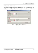
Use the [Browse] button to select the file. (Refer to “6.2 Setting Gang Writer Parameters.”)
9.3 When Programming Target System
•
A write error has occurred. (FAILURE)
(1) The debug pins (DCLK, DSIO, DST2) of the target MCU may not be correctly connected to the target
interface connector on the ICDmini.
Check the connection between the ICDmini and the target system. (Refer to “7.2 Connecting with Target
System.”)
(2) Noise may cause an error. Make sure that the wiring length between the target MCU and the ICDmini is as
short as possible (roughly 15 cm or shorter).
Provide a countermeasure against noise for the wiring pattern on the target board.
(3) There may be a difference in the interface voltage between the target system and the ICDmini.
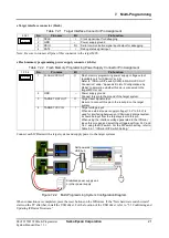
Set the DIP switch on the ICDmini, which allows selection of the interface voltage from 3.3 V, 1.8 V, or target
voltage input, appropriately. (Refer to “5.5 ICDmini Configuration.”)
(4) The flash programming voltage may not be supplied to the target MCU that needs an external flash
programming power supply.
Make sure that the target system is connected to the flash memory programming power supply connector
correctly. (Refer to “7.2 Connecting with Target System.”)
(5) The Gang Writer parameters may not be set to appropriate values.
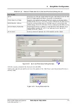
Configure them with an appropriate value. (Refer to “6.2 Setting Gang Writer Parameters.”)
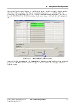
(6) The reset button on the ICDmini may be pressed after connection with the ICDmini is established by clicking
on the [ICDmini Connect] button.
If the reset button has been pressed, click on the [ICDmini Connect] button again after clicking on the
[ICDmini Disconnect] button once.
Summary of Contents for S5U1C17000Y23
Page 4: ......


