


Chapter 3 Installation and Configuration
S5U13L02P00C100 Evaluation Board User Manual (Rev. 1.0)
EPSON
7
Chapter 3 Installation and Configuration
The S5U13L02P00C100 Evaluation Board incorporates a DIP switch, jumpers, and 0 ohm resistors which allow it
to be used with a variety of different configurations.
3.1 Configuration DIP Switch
The S1D13L02 has 2 configuration inputs (CNF[2:1]). A DIP switch (SW1) is used to configure CNF[2:1] as
described below.
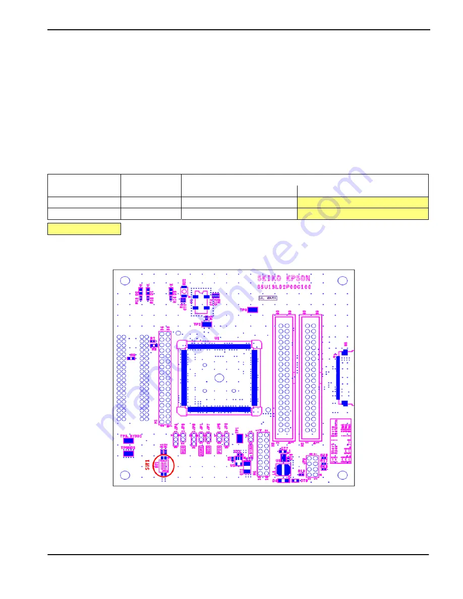
The following figure shows the location of DIP switch SW1 on the S5U13L02P00C100 Evaluation Board.
Figure 3-1: Configuration DIP Switch (SW1) Location
Table 3-1: Configuration DIP Switch Settings
S5U13L02P00C100
SW1-[2:1] Config
S1D13L02
CNF[2:1] Config
Power-On/Reset State
1 (ON)
0 (OFF)
SW1-[2]
CNF2
Big Endian
Little Endian
SW1-[1]
CNF1
Indirect 68
Indirect 80
= Required settings when using S5U13U00P00C100 USB Adapter board


