


Chapter 4 Technical Description
S5U13L02P00C100 Evaluation Board User Manual (Rev. 1.0)
EPSON
13
Note
H4 connector is not mounted. There is allocated space for the connector.
4.2 Clocks
The clock for the S1D13L02 LCD controlleris provided by a 4MHz oscillator.
Note
The on-board 4MHz oscillator is not specified to work below a 3.0V supply voltage.
4.3 Reset
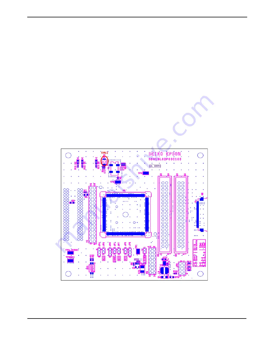
The S1D13L02 LCD controlleron the S5U13L02P00C100 Evaluation Board can be reset using a push-button switch
(SW2), or via an active low reset signal from the host development platform (pin 33 on the H1 connector).
Note
H1 connector is not mounted. There is allocated space for the connector.
Figure 4-1: Reset Switch (SW2)


