Push-Buttons and EPD Panel Connectors
S5U13C00P01C100 Board User Manual
Seiko Epson Corporation
11
(Rev. 1.0)
5.3
FPC Connector for ET011TT2 Connection (CN2)
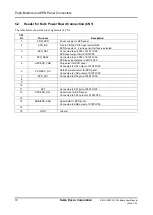
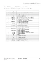
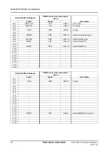
The following table shows the pinout and signal connections of the 24-pin FPC (CN2):
CN2 Pin
Pin
Connection
Description
1
EPD_P51
Connected to P06 port of S1D13C00.
2
FETG
GDR signal of EPD panel.
3
FETS
RESE signal of EPD panel.
4
VGL
VGL supply from EPD panel.
5
VGH
VGH supply from EPD panel.
6
EPD_TSCL
I2C clock for external temperature sensor on EPD panel.
7
EPD_TSDA
I2C data for external temperature sensor on EPD panel.
8
EPD_BS
Tied to VDD_EPD through resistor R49.
EPD bus select. 3-wire serial interface is selected.
9
EPD_BUSY
Connected to port P02 of S1D13C00.
EPD busy input status to S1D13C00.
10
EPD_RST
Connected to port P03 of S1D13C00.
EPD reset output from S1D13C00.
11
VCK/EPD_DC
Data/command select for EPD panel.
Connected to VCK output of S1D13C00.
12
HST/EPD_CSB
Chip-select for EPD panel.
Connected to HST output of S1D13C00.
13
VST/EPD_SCL
Serial clock for EPD panel.
Connected to VST output of S1D13C00.
14
ENB/EPD_SDA
Serial data for EPD panel.
Connected to ENB output of S1D13C00.
15
VDD_EPD
VC1 supply to EPD panel. (No-connect on panel side.)
16
VDD_EPD
VC1 supply to EPD panel.
17
GND
Ground.
18
VDD
VDD supply from EPD panel.
19
P07
Connected to P07 port of S1D13C00.
20
VSH
VSH supply from EPD panel.
21
PREVGH
PREVGH supply to EPD panel.
22
VSL
VSL supply from EPD panel.
23
PREVGL
PREVGL feedback from EPD panel.
24
VCOM_EPD
VCOM supply from EPD panel.

