5. Setting of DIP Switches
In order to suit the user’s specific requirements, desired control modes are
selectable by the two built-in DIP switches. The DIP switches (SW1 and SW2)
located on the control circuit board of the Printer are as shown in Fig. 54. To gain
access to the DIP switches, the upper case of the Printer must be removed.
NOTE: Turn the power off whenever you attempt to open up the printer case. Adequately
discharge static electricity which might be charged in your body, or it may cause
damages to internal electronic parts such as LSl’s, IC’s, etc.
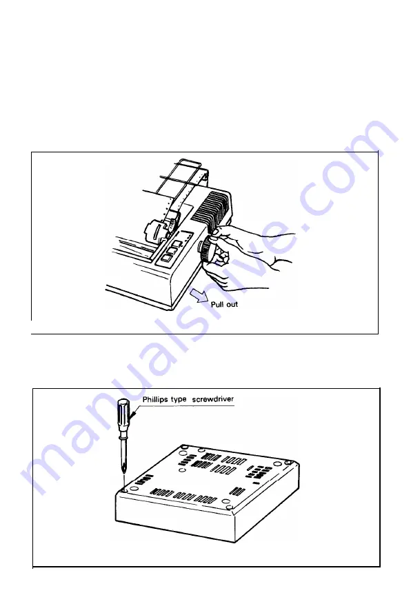
Remove the manual paper feed knob (black knob on the right side) by pulling it
straight out, with firm but steady pressure. (See Fig. 50.)
I
Fig. 50 Removing Manual Paper Feed Knob
Turn the printer upside down on a soft surface. With a Phillips type screwdriver
completely loosen all 4 screws. (See Fig. 51.)
Place tape over the 4 holes so the screws won’t fall off when you tip the printer
right side up.
Fig.
51 Loosening All 4 Screws
- 4 1 -
Summary of Contents for M X - 8
Page 1: ...M X 8 0 EPSON DOT MATRIX PRINTER TYPE II Operation Manual EPSON P8190014 2 ...
Page 22: ... 1 6 ...
Page 41: ... 3 5 ...
Page 44: ...1 3 Printer initial check Take the following steps and become familiar with the Printer 3 8 ...
Page 55: ...Fig 57 Setting Form Length per Page 4 9 ...
Page 56: ...Fig 58 Setting Number of Columns per Line 5 0 ...
Page 57: ...Fig 59 Setting Skip over Perforation Function 5 1 ...
Page 80: ... 2 Normal density bit image printing 74 ...
Page 89: ......
Page 90: ...Fig Al 2 Driver Circuit Diagram 8 5 ...
Page 96: ......
Page 97: ...APPENDIX 4 Character Fonts 92 ...
Page 98: ...NOTE Numbers represent Hex code 93 ...
Page 99: ... 94 ...
Page 100: ... 95 ...
Page 101: ...APPENDIX 5 Control Codes ...


