background image

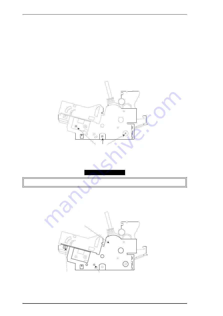
3.2.10.3 Removing the Right Frame Assembly

1.

Remove the rear/front edge guide assembly, front cover, paper eject assembly, rear/front tractor
unit, and printer cover (see Section 3.2.1).

2.

Remove the panel board (see Section 3.2.2) and upper housing assemblies (see Section 3.2.7).

3

Remove the printer mechanism (see Section 3.2.10 ), CR motor assembly (see Section 3.2.9), PF
motor, (see Section 3.2.10.1) and PG sensor assembly (see Section 3.2.10.2 ).

4.

Remove the hexagon nut (standard, M4) securing the gap adjust lever. Then, remove the gap
adjust lever from the right frame assembly.

5.

Remove 2 CBS screws (3

×

6, F/Zn) securing the platen cover.

6.

Remove 3 CBS screws (3

×

6, F/Zn) securing the right frame assembly at the positions illustrated.

7.

Remove the right frame assembly.

Assembly Notes

Adjust the platen gap and bidirectional print alignment. Refer to Chapter 4.

3.2.10.4 Disassembling the Right Frame Assembly

1.

Remove 1 CBS screw (3

×

6, F/Zn ) and 1 CBS screw (3

×

8, F/Zn) securing the right sub frame.

(The bold line in the illustration is the right sub frame.)

CBS Screw (3 x6) Securing the Right Frame Assembly

Figure 3-20 Removing the Right Frame Assembly

CBS Screw (3 X6 FZ/n ) 
Securing the Right Sub Fram

CBS Screw (3 x 8 F/Zn) 
Securing the Right Sub Frame

Right Sub Frame

Figure 3-21 Removing the Right Sub Frame

Disassembly and Assembly

LQ-2170 Service Manual

3-16

Rev.A

Summary of Contents for LQ-2170

Page 1: ...EPSON TERMINAL PRINTER LQ 2170 SERVICE MANUAL EPSON 4005735 ...

Page 2: ...ject to change without notice All efforts have been made to ensure the accuracy of the contents of this manual However should any errors be detected SEIKO EPSON would greatly appreciate being informed of them The above notwithstanding SEIKO EPSON can assume no responsibility for any errors in this manual or the consequences thereof Copyright 1995 by SEIKO EPSON CORPORATION Nagano Japan ...

Page 3: ...O NOT CONNECT THE UNIT TO A POWER SOURCE UNIT INSTRUCTED TO DO SO WHEN THE POWER SUPPLY CABLE MUST BE CONNECTED USE EXTREME CAUTION IN WORKING ON POWER SUPPLY AND OTHER ELECTRONIC COMPONENTS WARNING 1 REPAIRS ON EPSON PRODUCT SHOULD BE PERFORMED ONLY BY AN EPSON CERTIFIED REPAIR TECHNICIAN 2 MAKE CERTAIN THAT THE SOURCE VOLTAGE IS THE SAME AS THE RATED VOLTAGE LISTED ON THE SERIAL NUMBER RATIG PLA...

Page 4: ...re organized as follows Chapter 1 Provides a general product overview Lists specifications and illustrates the main components of the printer Chapter 2 Describes the theory of printer operation Chapter 3 Includes a step by step guide for product disassembly and assembly Chapter 4 Includes a step by step guide for addjustement Chapter 5 Provides Epson approved techniques for troubleshooting Chapter...

Page 5: ...REVISION SHEET Revision Issued Date Revision Page Rev A December 5 1995 1st issued ...

Page 6: ...TABLE OF CONTENTS CHAPTER 1 GENERAL DESCRIPTION CHAPTER 2 OPERATION PRINCIPLES CHAPTER 3 DISASSEMBLY AND ASSEMBLY CHAPTER 4 ADJUSTMENTS CHAPTER 5 TROUBLESHOOTING CHAPTER 6 MAINTENANCE APPENDIX ...

Page 7: ... 3 2 Interface Specifications 1 21 1 3 2 1 Parallel Interface Forward Channel 1 21 1 3 2 2 Parallel Interface Reverse Channel 1 23 1 3 2 3 Interface Selection 1 24 1 3 2 4 Preventing the Host from Data Time out 1 24 1 3 3 Paper Handling Firmware Specifications 1 25 1 3 4 Paper Width Sensor Operation 1 28 1 4 Operating Instructions 1 29 1 4 1 Control Panel Operation 1 29 1 4 2 Status Codes Indicate...

Page 8: ...able Area for Envelopes and Card Stock 1 11 Figure 1 5 Printable Area for Continuous Paper 1 13 Figure 1 6 Label Size 1 14 Figure 1 7 Printable Area for Roll Paper 1 15 Figure 1 8 Data Transmission Timing 1 22 Figure 1 9 Control Panel 1 29 Figure 1 10 Self test Printout 1 32 Figure 1 11 Hexadecimal Dump Printout 1 32 Figure 1 12 Main Components 1 35 Figure 1 13 C165 MAIN Board Assembly 1 36 Figure...

Page 9: ...le 1 20 Electrical Specifications for 120 V Version 1 16 Table 1 21 Electrical Specifications for 220 240 V Version 1 16 Table 1 22 Environmental Conditions 1 17 Table 1 23 Reliability 1 17 Table 1 24 Safety Information for Printer Models 1 17 Table 1 25 CE Marking 1 18 Table 1 26 Physical Specifications 1 18 Table 1 27 Hopper Capacity 1 18 Table 1 28 Stacker Capacity 1 19 Table 1 29 Environmental...

Page 10: ...aper multipart paper envelopes card stock labels roll paper Fonts 9 LQ and 1 draft bitmap typefaces 8 barcode fonts Character tables Standard version 11 tables NLSP version 20 tables Input buffer 64KB Acoustic noise 53 dB A ISO 7779 pattern Reliability Total print volume 7 5 million lines except printhead MTBF 6000 power on hours POH Printhead life 400 million strokes wire Ribbon life 8 million ch...

Page 11: ...Figure 1 1 Exterior View of the LQ 2170 Product Description LQ 2170 Service Manual 1 2 Rev A ...

Page 12: ...Unit Description High capacity cut sheet feeder 1 bin 1 C80673 Second bin cut sheet feeder 2 bin 2 C80674 Pull tractor unit C80032 Roll paper holder 8310 Serial I F card C82305 C82306 32KB intelligent serial I F card C82307 C82308 32KB intelligent parallel I F card C82310 C82311 Local Talk I F card C82312 32KB IEEE 488 I F card C82313 Coax I F card C82314 Twinax I F card C82315 Ethernet I F card C...

Page 13: ...m 0 00083 inch The figure above shows the configuration of pins on the paper Print direction Bidirectional with logic seeking for text and unidirectional for graphics Bidirectional printing of graphics can be selected with a printer setting or software command 0 847 mm 1 30 0 353 mm 1 72 2 822 mm 8 72 1 2 3 4 5 6 7 8 9 10 11 12 13 14 15 16 17 18 Head Center Figure 1 2 Pin Configuration Product Des...

Page 14: ...3 12 cpi 163 132 88 15 cpi 204 165 110 LQ Condensed 17 cpi 233 189 126 20 cpi 272 220 147 Resolution Table 1 5 Print Resolution Print Mode Horizontal Density Vertical Density Adjacent Dot Printed High speed draft 90 dpi 180 dpi No Draft 120 dpi 180 dpi No Draft condensed 240 dpi 180 dpi No NLQ 360 dpi 180 dpi No 8 pin bit image 60 80 90 or 120 dpi 60 dpi Yes 120 or 240 dpi 60 dpi No 24 pin bit ima...

Page 15: ... 0 inches sec Release lever Set the release lever using the following table Table 1 6 Paper Path and Paper Types Lever Position Paper Entrance Paper Types Single Sheet Labels Card Stock Envelopes Multipart Roll Paper Friction Front insertion OK NO OK OK NO Rear insertion OK NO OK OK NO CSF bin 1 OK NO OK OK NO CSF bin 2 OK NO NO NO NO Roll paper holder NO NO NO NO OK Front tractor Push OK OK NO OK...

Page 16: ...n 1 6 inch after the paper end has been detected Use the paper tension unit Insert the multipart cut sheet forms only from the front 2 Push tractor feed Set the release lever to the REAR PUSH FRONT PUSH position and install the paper eject assembly Load paper from the rear or front entrance Release the friction feed mechanism Multipart paper must be carbonless Use the paper tension unit Do not per...

Page 17: ...5 101 mm 4 0 420 mm 16 5 Length 147 mm 5 8 420 mm 16 5 101 mm 4 0 420 mm 16 5 Thickness 0 065 mm 0 0025 0 14 mm 0 0055 0 065 mm 0 0025 0 14 mm 0 0055 Weight 52 3 g m2 14 lb 90 g m2 24 lb 52 3 g m2 14 lb 90 g m2 24 lb Quality Plain paper recycled paper Not curled folded or crumpled Plain paper recycled paper Not curled folded or crumpled Table 1 9 Specifications for Cut Sheets Multipart Front Entry...

Page 18: ... 3 mm 0 12 or more PW 364 mm 14 33 25 mm 0 98 or more PW 420 mm 16 5 3 mm 0 12 or more PW 364 mm 14 33 25 mm 0 98 or more PW 420 mm 16 5 RM right margin 3 mm or more PW 364 mm 14 33 25 mm 0 98 or more PW 420 mm 16 5 3 mm or more PW 364 mm 14 33 25 mm 0 98 or more PW 420 mm 16 5 TM top margin 4 2 mm 0 17 or more 4 2 mm 0 17 or more BM bottom margin 4 2 mm 0 17 or more 4 2 mm 0 17 or more BM TM PL P...

Page 19: ...es is available only at normal temperatures and humidity Insert envelopes from the rear entrance only Insert the longer side of the envelope horizontally Table 1 12 Specifications for Card Stock Front Entry Rear Entry Minimum Maximum Minimum Maximum Width 105 mm 4 13 148 mm 5 83 105 mm 4 13 148 mm 5 83 Length 148 mm 5 83 148 mm 5 83 105 mm 4 13 148 mm 5 83 Thickness 0 22 mm 0 0087 0 22 mm 0 0087 W...

Page 20: ...Refer to Table 1 12 PL length Refer to Table 1 11 Refer to Table 1 12 LM left margin 3 mm 0 12 or more 3 mm 0 12 or more RM right margin 3 mm 0 12 or more 3 mm 0 12 or more TM top margin 4 2 mm 0 17 or more 4 2 mm 0 17 or more BM bottom margin 4 2 mm 0 17 or more 4 2 mm 0 17 or more Printable area RM TM BM LM PW LM RM TM BM PL Printable area PW PL Figure 1 4 Printable Area for Envelopes and Card S...

Page 21: ...hickness 0 065 mm 0 0025 0 39 mm 0 015 0 065 mm 0 0025 0 39 mm 0 015 0 065 mm 0 0025 0 39 mm 0 015 Weight not multipart 52 3 g m2 14 lb 82 g m2 22 lb 52 3 g m2 14 lb 82 g m2 22 lb 52 3 g m2 14 lb 82 g m2 22 lb Weight one sheet of a multipart form 40 g m2 12 lb 58 g m2 15 lb 40 g m2 12 lb 58 g m2 15 lb 40 g m2 12 lb 58 g m2 15 lb Types of paper Plain paper Recycled paper Carbonless multipart Plain ...

Page 22: ...s Paper Abbreviations Continuous Paper PW width Refer to Table 1 14 PL length Refer to Table 1 14 LM left margin 13 mm 0 51 or more RM right margin 13 mm 0 51 or more TM top margin 4 2 mm 0 17 or more BM bottom margin 4 2 mm 0 17 or more PW LM RM TM BM PL Printable area Figure 1 5 Printable Area for Continuous Paper LQ 2170 Service Manual Product Description Rev A 1 13 ...

Page 23: ... mm 0 0075 0 16 mm 0 0063 0 19 mm 0 0075 Label weight 68 g m2 17 lb 68 g m2 17 lb Quality Avery continuous form labels Avery mini line or equivalent quality labels Avery continuous form labels Avery mini line or equivalent quality labels Printing on labels is available only at normal temperatures and humidity The base sheet for the labels must be continuous paper Continuous paper with labels shoul...

Page 24: ...2 3 g m2 14 lb 82 g m2 22 lb Quality Plain paper recycled paper Not curled folded or crumpled Printable area Figure 1 7 gives the printable area for roll paper Each abbreviation is defined in the following table Table 1 18 Printable Area for Roll Paper Abbreviations Roll Paper PW width See Table 1 17 PL length See Table 1 17 LM 3 mm 0 12 or more RM 3 mm 0 12 or more TM 4 2 mm 0 17 or more BM 4 2 m...

Page 25: ... Rated current 1 0 A max 2 6 A Power consumption Approx 62 W self test in draft mode at 10 cpi Insulation resistance 10 MΩ min between AC line and chassis 500 VDC Dielectric strength 1000 VAC rms 1 min or 1200 VAC rms 1 sec between AC line and chassis Table 1 21 Electrical Specifications for the 220 240 V Version Item Specifications Rated voltage 220 to 240 VAC Input voltage range 198 to 264 VAC R...

Page 26: ...ondensation 2 During printing on multipart paper envelopes card stock or labels 3 In shipment container 1 2 8 Reliability Table 1 23 gives maximum life and usage specifications Table 1 23 Reliability Statistics Item Specification Total print volume 7 5 million lines except printhead MTBF 6000 power on hours POH Printhead life 400 million strokes wire Ribbon life 8 million characters 1 2 9 Safety A...

Page 27: ...F can be connected to the high capacity CSF to allow them to be used as a double bin CSF The following table provides the specifications for these CSF options Hopper capacity Table 1 27 Hopper Capacity CSF Bin 1 CSF Bin 2 Single sheets 150 sheets 1 110 sheets 2 185 sheets 3 135 sheets 4 50 sheets 1 50 sheets 2 60 sheets 3 60 sheets 4 Envelopes 25 sheets 5 30 sheets 6 Card stock 50 sheets 7 Multipa...

Page 28: ...g m2 51 lb thickness 0 22 mm 0 0087 6 1 original 5 copies thickness 0 36 mm 0 0142 Reliability MCBF 2 105 cycles Environmental conditions Table 1 29 Environmental Conditions Operating Non Operating Temperature 5 to 35 C 41 to 95 F 30 to 60 C 22 to 140 F Humidity 15 to 80 RH 1 3 30 to 605 RH 2 4 5 to 85 RH 3 1 Single sheets plain 64 g m2 weight 82 g m2 17 lb weight 22 lb 2 Single sheets plain weigh...

Page 29: ... A UPC E Code 39 Code 128 POSTNET International character sets 13 countries U S A France Germany U K Denmark 1 Sweden Italy Spain 1 Japan Norway Denmark2 Spain2 Latin America Character tables The standard version has 11 character tables and the NLSP version has 20 character tables as shown in the following table Table 1 30 Character Tables Version Character Tables Standard Version Italic PC 437 U ...

Page 30: ...In bit 2 5 DATA4 23 In bit 3 6 DATA5 24 In bit 4 7 DATA6 25 In bit 5 8 DATA7 26 In bit 6 9 DATA8 27 In bit 7 MSB 10 ACKNLG 28 Out This signal negative pulse indicates the printer has received data and is ready to accept more data 11 BUSY 29 Out This signal s HIGH level means the printer is not ready to accept data 12 PE 28 Out This signal s HIGH level means the printer has a paper out error 13 SLC...

Page 31: ...nal is active LOW level During hardware initialization In self test mode In adjustment mode In default setting mode The ERROR signal is active LOW level under the conditions below If there is a fatal error If there is a paper out error If the cover is open cover open error PE signal is active HIGH level under the conditions below If there is a paper out error data byte n data byte n 1 t hold tsetu...

Page 32: ... 8 DATA7 26 In bit 6 9 DATA8 27 In bit 7 MSB 10 PtrClk 28 Out Printer clock signal 11 PtrBusy DataBit 3 7 29 Out Printer busy signal and reverse channel transfer of data bits 3 or 7 12 AckDataReq DataBit 2 6 28 Out Acknowledge data request signal and reverse channel transfer of data bits 2 or 6 13 Xflag DataBit 1 5 28 Out X flag signal and reverse channel transfer of data bits 1 or 5 14 HostBusy 3...

Page 33: ... printer interface is busy the selected interface remains active Interface state and interface selection When the parallel interface is not selected that interface goes into a busy state When the Type B serial interface card is installed and it is not selected the interface sends an XOFF code and sets the DTR signal to MARK When the optional interface is not selected the printer sends disable comm...

Page 34: ...tatus The rear PE sensor detects that paper is loaded in the rear paper path The release lever is set to continuous paper Table 1 35 Paper Handling Sequence 2 Occurrence Result Pause button pressed The printer goes off or on line LF FF button pressed The printer performs a line feed LF FF button held down continuously The printer performs a form feed after the line feed Load Eject button pressed P...

Page 35: ...that paper was loaded in the rear paper path The beeper sounds Printer status Printer is on line not in the pause state No PE sensor detects that paper is loaded The printer is set to CSF The release lever is set to the Friction Table 1 37 Paper Handling Sequence 4 Occurrence Result Print command sent The paper is loaded from the CSF Pause button pressed Printer goes off line LF FF button pressed ...

Page 36: ...ter micro feeds paper backward Release lever set to the tractor position The beeper sounds Front paper end sensor detects that paper was loaded in the rear paper path The beeper sounds Printer status Front PE sensor detects that paper is loaded in the rear paper path The release lever position is set to Friction Table 1 39 Paper Handling Sequence 6 Trigger Result Pause button pressed Printer goes ...

Page 37: ...n in the following table Table 1 40 PW Sensor Operation Paper Path Paper Width Measurement Image Cut Function Friction Measured Executed Only Copy Mode 2 Push Tractor Rear Front Measured Not Executed 1 Pull Tractor Measured Not Executed 1 1 The measured paper width value is used to estimate the printhead centering position When narrow continuous paper fewer than 30 columns is loaded the printer ch...

Page 38: ...rinting and non printing states Enables the micro adjust function when held down for 3 seconds Load Eject Loads or ejects paper Micro feeds forward when that function is enabled LF FF Line feed when pressed briefly Form feeds when held down for a few seconds Micro feeds backward when that function is enabled Tear Off Bin Advances continuous paper to the tear off position Selects CSF bin 1 2 or car...

Page 39: ...ton Function Pitch Selects the menu Tear Off Bin Changes the setting Others Not available 1 4 2 Status Codes Indicated by the LEDs and Beeper Table 1 44 Indicators and Beeper Pause Paper Out Tear Off Bin Pitch Font Beeper Pause On Paper Out On On Paper Jam On Blinks Head Hot Blinks Cover Open On Micro Adjust Blinks Tear Off Bin Selection Pitch Selection Font Selection Fatal Error Blinks Blinks Bli...

Page 40: ...s turned off the setting is not cleared Conditions required for the adjustment Auto tear off function Auto tear off has been set to ON in default setting mode The release lever has been set to Tractor The data buffer is empty and the printer is on line More than 3 seconds have passed after the host computer finished transferring print data Manual tear off function Auto tear off has been set to OFF...

Page 41: ...dividually when a dual bin CSF is in use The self test prints out the following The maximum number of printable lines only on cut sheets from the CSF The pattern of characters shown in the figure below 1 4 6 Hexadecimal Dump Function Pressing the Load Eject and LF FF buttons while turning on the printer puts the printer in hexadecimal dump mode In this mode data received is printed out in hexadeci...

Page 42: ...tory settings This operation initializes the items below to the factory settings in the right hand column Table 1 45 EEPROM Initialization Settings Setting Factory Default Font Roman Pitch 10 CPI Character Table PC437 Other Font Selection Roman T Page Format Tractor Rear Front Page Length 11 inches TOF Position 8 5 mm 0 333 inches Bottom Margin 11 inches Page Format Friction CSF Bin 1 Bin 2 Manual...

Page 43: ...l code ESC This initialization Clears unprinted data Resets the printer s setting defaults 1 5 2 Operation Initialization This initialization is activated by receipt of the INIT signal negative pulse This initialization Clears the buffer of all data Cancels download character definition Puts the printer in standby state if no errors occur Executes software initialization 1 5 3 Power On Initializat...

Page 44: ...ir The main components are C165 MAIN Board Assembly C165 PSB PSE Board Assembly 120 V 230 V C165 PNL Board Assembly Printer Mechanism Housing Assembly The following figure shows the main components of the LQ 2170 Figure 1 12 Main Components LQ 2170 Service Manual Product Description Rev A 1 35 ...

Page 45: ...idge etc The power supply board provides 5 VDC and 35 VDC for the main board and printer mechanism UDN2917EB IC11 PF Motor Driver IC12 CR Motor Driver SLA7024M Head Drive TRANSISTOR CN2 for Option I F IC 1 CPU TMP96C041AF IC 2 GATE ARRAY E05B13 IC 5 PS RAM EEPROM IC3 P ROM Figure 1 13 C165 MAIN Board Assembly PC1 Photo Coupler F1 Fuse IC51 Switching Regulator TL494CN Transformaer T1 Q1 Switching F...

Page 46: ...e LQ 2170 1 6 4 Printer Mechanism The printer mechanism consists of an 24 pin impact dot head paper feed PF motor ribbon feed RF motor paper end PE sensor home position HP sensor platen gap PG sensor release lever sensor etc Power SW SW SW SW SW SW SW LED LED LED LED LED Figure 1 15 Board Assembly C165 PNL Figure 1 16 Printer Mechanism LQ 2170 Service Manual Product Description Rev A 1 37 ...

Page 47: ...6 5 Housing Assembly This consists of printer cover assembly edge guide assembly upper housing lower housing assembly etc Figure 1 17 Housing Assembly Product Description LQ 2170 Service Manual 1 38 Rev A ...

Page 48: ...er Advance Mechanism 2 5 2 1 5 Paper Paths 2 11 2 1 6 Ribbon Advance Mechanism 2 16 2 2 POWER SUPPLY OPERATION 2 17 2 2 1 Power Supply Overview 2 17 2 2 2 Power Supply Circuit Operation 2 18 2 3 CONTROL CIRCUIT 2 22 2 3 1 Control Circuit Operation Overview 2 22 2 3 2 System Reset Circuit 2 24 2 3 3 Printhead Drive Circuit 2 24 2 3 4 CR Motor Drive Circuit 2 25 2 3 5 PF Motor Drive Circuit 2 26 2 3...

Page 49: ... Figure 2 19 Pull Tractor Feeding Using the Front Entrance 2 15 Figure 2 20 Push Pull Tractor Feeding Using the Front Entrance 2 15 Figure 2 21 Ribbon Advance Mechanism 2 16 Figure 2 22 Power Supply Circuit Block Diagram 2 17 Figure 2 23 Power Switch Circuit 2 18 Figure 2 24 Over Voltage Protection Circuit 2 18 Figure 2 25 35V Line Constant Voltage Control Circuit 2 19 Figure 2 26 35V Line Overloa...

Page 50: ...ard the platen 3 When the dot wire impacts the platen pressing against the ribbon and paper it prints a dot 4 When the driving voltage stops energizing the coil the magnetic force from the iron core vanishes The actuating plate returns to its original position the position before coil was energized with spring action The dot wire also returns to its original position This is the sequence used to p...

Page 51: ...asis for determining the carriage position The HP sensor informs the CPU when the carriage is at the home position The sensor is ON when the carriage is pushed to the right or left The striker on the carriage activates the sensor to indicate the carriage is at the home position which toggles the sensor to OFF Table 2 1 CR Motor Assembly Specifications Category Requirement Type 4 phase 200 pole HB ...

Page 52: ... 3 normal to protect the printhead The following table show you the relationship between the platen gap and the print speed Table 2 2 Platen Gap and Print Speed Paper Type Paper Thickness mm Adjust Lever Position PG SW Print Speed Single Sheet 0 065 0 Closed Normal 0 1 0 Closed Normal 0 14 1 Closed Normal Continuous Paper Single Sheet 0 065 0 Closed Normal 0 09 0 Closed Normal Continuous Paper Mul...

Page 53: ...ition moves the paper guide rollers and the new lever position is detected by 2 release switch sensors RLSW1 and RLSW2 See the following table Table 2 3 Release Lever Position Release Lever Position Status of Paper Guide Rollers RL SW 1 RL SW 2 Friction mode The paper guide rollers are pressed against the platen Open Open Front push tractor mode The paper guide rollers are separated from the plate...

Page 54: ...ck arrow driving the paper advance reduction gear The paper advance reduction gear turns the platen gear and paper tension roller gear Paper advances in the direction of the white arrow Figure 2 5 shows the friction advance method when paper is fed through the top paper entrance In the friction advance method the paper guide roller spring holds the paper against the platen Paper can be released by...

Page 55: ...mitted to the push tractor gear through the PF motor pinion gear paper advance reduction gear platen gear and gear train in the front part of the printer When the PF motor pinion gear turns in the direction of the black arrow the tractor gear rotates in the direction of the black arrow and thus feeds paper into the printer Paper is advanced by the paper drive roller and platen which are also drive...

Page 56: ...Figure 2 7 Push Tractor Operation Using the Front Paper Entrance LQ 2170 Service Manual Operating Principles Rev A 2 7 ...

Page 57: ...ter On the other hand the pull tractor is installed at the paper exit and pulls paper out of the printer mechanism As a result the paper tension unit is not required Figure 2 8 illustrates pull tractor operation when paper is fed through the bottom paper entrance Figure 2 8 Pull Tractor Operation Using the Bottom Paper Entrance Operating Principles LQ 2170 Service Manual 2 8 Rev A ...

Page 58: ...er entrance They operate simultaneously to push and pull the paper through the printer mechanism Figure 2 9 illustrates push pull tractor operation when paper is fed through the rear paper entrance Figure 2 10 illustrate push pull tractor operation when paper is fed through the front entrance Figure 2 9 Push Pull Tractor Operation Using the Rear Paper Entrance LQ 2170 Service Manual Operating Prin...

Page 59: ...Figure 2 10 Push Pull Tractor Operation Using the Front Paper Entrance Operating Principles LQ 2170 Service Manual 2 10 Rev A ...

Page 60: ...e 2 11 Paper Paths and PE Sensor Locations 1 Top Entrance Figure 2 12 shows the paper path for friction feed using the top entrance The top entrance is only used with the friction feed method When the top entrance is used the rear PE sensor detects when the paper is out Figure 2 12 Friction Feeding Using the Top Entrance Up Up Rear Driven PF Roller Front Driven PF Roller Lower Driven PF Roller Rea...

Page 61: ... feed When you use the rear entrance the rear PE sensor detects when paper is out Figure 2 13 Push Tractor Feeding Using the Rear Entrance Figure 2 14 Pull Tractor Feeding Using the Rear Entrance As shown above in Figure 2 14 when you use the pull tractor in this printer you must remove the paper eject cover which includes the paper tension roller from the printer mechanism Down Down Operating Pri...

Page 62: ... paper tension roller from the printer mechanism 3 Bottom Entrance Figure 2 16 shows the paper path for tractor feeding using the bottom entrance The bottom entrance is used only for pull tractor feed When the bottom entrance is used the front PE sensor detects when paper is out Figure 2 16 Pull Tractor Feeding Using the Bottom Entrance Down LQ 2170 Service Manual Operating Principles Rev A 2 13 ...

Page 63: ...paper feed methods friction feed push tractor feed pull tractor feed or push pull tractor feed When the front entrance is used the front PE sensor detects when paper is out Figure 2 17 Friction Feeding Using the Front Entrance Figure 2 18 Push Tractor Feeding Using the Front Entrance Up Up Operating Principles LQ 2170 Service Manual 2 14 Rev A ...

Page 64: ...Figure 2 19 Pull Tractor Feeding Using the Front Entrance Figure 2 20 Push Pull Tractor Feeding Using the Front Entrance Down LQ 2170 Service Manual Operating Principles Rev A 2 15 ...

Page 65: ...use a planetary gear is used in the gear linkage Table 2 4 Ribbon Advance Gear Linkage Direction of Carriage Movement Gear Linkage Left to right indicated by the black arrow Belt driven pulley Gear 1 Gear 2 Ribbon driving gear Right to light indicated by the white arrow Belt driven pulley Gear 1 Gear 3 Gear 4 Ribbon driving gear The ribbon brake spring attached to the exit of the cartridge case pr...

Page 66: ... the power supply circuitry As shown in the figure above when AC power enters the printer from an external power source the filter circuit removes the noise The AC voltage then undergoes full wave rectification and is smoothed to produce direct voltage The voltage is fed to the gate port for the switching FET Q1 K1531 or K1692 through resistors R18 and R31 and then the switching circuit operates T...

Page 67: ...C Line Over Voltage Protection Circuit This circuit is shown below The 35 VDC over voltage protection circuit operates when voltage exceeds 42 42 V between ZD52 and ZD87 and shuts off the switching FET Q1 K1692 or K1531 The 5 VDC over voltage protection circuit operates when voltage exceeds 7 5 V between ZD53 and shuts off the switching FET Q1 K1692 or K1531 When either of these protection circuit...

Page 68: ...g maintained In this condition the forward current of PC1 drops to 0 A Consequently voltage Vf between PC1 and D81 also drops On this circuit when the Vf voltage drops below 1 3 V 35 V line 33 1 V IC528 detects the overload and outputs the PWDN signal 5 V HIGH active to port 20 of the CPU When the CPU receives this PWDN signal printing stops When the 35 V line becomes normal again the voltage betw...

Page 69: ...ent control circuit is shown below Port 2 of IC51 TL494CN monitors the 5 V line and this protection circuit operates when the 5 V line goes below 4 75 V When this circuit operates port 8 signal output of the PWM pulse stops and Q51 stops its switching operation Consequently the 5 V line stops generating 35V Line GND Q53 R70 R71 R72 R73 Q54 Q82 C57 R74 R75 R54 R68 3 4 6 5 D85 Q31 PSC Figure 2 27 35...

Page 70: ... is input into port 15 When the voltage of port 16 goes below 4 81 V or above 5 17 V the pulse width of the PWM signal which is output from port 8 changes and the 5 V line is kept between 4 81 V to 5 17 V 5v Line GN D R53 R88 R64 R65 IC51 TL494CN D51 L51 8 R51 R61 Q51 16 15 35V R81 R59 R60 ZD55 GND GND Figure 2 29 5 V Line Constant Voltage Control Circuit LQ 2170 Service Manual Operating Principle...

Page 71: ... Version It oversees control of all the components in the printer The following chart shows you a block diagram of the control circuit Gate Array CPU CSF Drv CSF Detector PE Rear Detector PE Front Detector P Width Detector Home Detector Release Lever Detector Gap Lever Detector 35V Voltage Detector Head Drv Head Temp Detector ROM RAM EEPROM Rest IC PF Drv CR Drv Panel LED Power SW Parallel I F Typ...

Page 72: ... latch of the address data bus from the CPU Clock control unit Bit manipulation Interface control Expanded parallel port Printhead control Motor control EEPROM IC 8 An electrically writable and erasable ROM used to hold such information as the TOF position and bidirectional adjustment value ROM IC 3 The ROM contains the program that runs the CPU and holds the character design also called the chara...

Page 73: ...ne the printhead drive pulse width Using the monitored voltage the CPU converts the voltage to a digital value and decides the printhead drive pulse width and then transports the data to the gate array via CPU port 19 Based on the monitored voltage the CPU decides the printing interval Port 73 monitors the printhead temperature to protect the printhead If the temperature exceeds 110 C 228 F printi...

Page 74: ...40 1 2 Super draft Copy Power down Draft Copy Power down LQ 3 4 82 5 1980 1 2 Bit Image Power down 2 3 73 4 1760 1 2 LQ Copy 1 2 52 5 1320 1 2 LQ Power down LQ Copy Power down The SLA7024M IC12 CR motor driver circuit detects and regulates the amount of current flowing in the carriage motor coil The current flowing through the coil varies depending on the speed of the CR motor The CPU sets the amo...

Page 75: ...circuit The EEPROM is controlled by CPU ports 9 P70 10 P71 11 P72 and 12 P73 Port 11 is the data output line used to save the information to the EEPROM and port 12 is the data input line used to read the saved data from the EEPROM Port 70 is the chip select line and port 71 is the clock timing line When the PWDN signal power down is detected on port 20 INTO the CPU writes the necessary data to the...

Page 76: ...ys are cut off by the printhead The rear PE sensor detects that paper has been loaded when the photo diode rays are cut off by the sensor plate which is included in the rear PE sensor The PW sensor used for paper width measurement and paper loading positioning detects the paper edge by comparing the measured voltage with standard voltage which was measured during the power on sequence Additionally...

Page 77: ...ving the PF Motor Assembly 3 14 3 2 10 2 Removing the PG Sensor Assembly 3 15 3 2 10 3 Removing the Right Frame Assembly 3 16 3 2 10 4 Disassembling the Right Frame Assembly 3 16 3 2 10 5 Removing the Left Frame Assembly 3 19 3 2 10 6 Removing the Ribbon Drive RD Assembly 3 20 3 2 10 7 Removing the CR Assembly 3 21 3 2 10 8 Removing the Rear PE Sensor Assembly 3 23 3 2 10 9 Removing the Front PE S...

Page 78: ...Figure 3 23 Engaging Gears 2 3 18 Figure 3 24 Engaging the Tractor Clutch Cam 3 18 Figure 3 25 Removing the Left Frame Assembly 3 19 Figure 3 26 Cable Connection for the Release Lever Sensors 3 19 Figure 3 27 Removing the RD Assembly 3 20 Figure 3 28 Engaging Gears for the RD Assembly 3 20 Figure 3 29 Disconnecting the FFC 3 21 Figure 3 30 Removing the CR Assembly 3 21 Figure 3 31 Inserting the Ti...

Page 79: ... Removing the E ring and 2 CBS Screws 3 32 Figure 3 52 Removing the Paper Feed Roller Cover 3 32 List of Tables Table 3 1 Recommended Tools 3 1 Table 3 2 Equipment Required for Maintenance 3 1 Table 3 3 Inspection Check List for Repaired Printer 3 2 Table 3 4 Screw Types and Abbreviations 3 3 ...

Page 80: ......

Page 81: ...ration Use only recommended tools for maintenance work Use only recommended lubricants and adhesives see Chapter 6 Adjust the printer only in the manner described in this manual 3 1 2 Tools Tables 3 1 and 3 2 list the tools recommended for disassembling assembling or adjusting the printer Use only tools that meet these specifications Table 3 1 Recommended Tools Tool Part No Round nose pliers B7404...

Page 82: ...necessary Paper path Is the type of paper in the printer feeding smoothly Checked Not necessary Is the tractor feeding the paper correctly Checked Not necessary Is the paper path clear of all obstructions Checked Not necessary Is the platen free of damage Checked Not necessary Ribbon mask Is the ribbon mask free of distortion Checked Not necessary Self test Was the self test successful Checked Not...

Page 83: ...ind head B tight screw CBS Cross recessed bind head S tight screw CBN Cross recessed bind head N tight screw CBC Cross recessed bind head C Lamitite screw CBA Cross recessed bind head A lamitite screw CB O Cross recessed bind head with outside toothed lock washer Cross recessed head Bind Normal Top Side with Notch S tight B tight C lamitite A lamitite Pan Body Head Figure 3 1 Screw Types and Abbre...

Page 84: ...printer s power cord and interface cable 3 2 1 Page 3 5 Before Starting Disassembly Pricedure 3 2 2 Page 3 6 Removing the Panel Board Assembly 3 2 7 3 2 3 Removing the Printhead 3 2 4 Removing the HP Sensor Page 3 8 Page 3 11 Removing the Printer Mechanism 3 2 10 1 Page 3 14 3 2 10 2 Page 3 15 Removing PG Sensor 3 2 12 Page 3 25 Removing C165 MAIN Board Removing C165 PSB E Board Removing the PW Sn...

Page 85: ...assembly Front rear tractor assembly Ribbon cartridge Refer to the following figure Note Remove the paper eject cover and the front rear tractor assembly by pushing to release the hooks at both sides When remounting them be sure to snap the hooks on the projecting parts Figure 3 3 Before Starting Disassembly Procedures LQ 2170 Service Manual Disassembly and Assembly Rev A 3 5 ...

Page 86: ... 4 Remove the panel board assembly from the upper housing assembly Assembly Notes Before disconnecting the FFC from CN1 slide the lock cover for CN 1 as shown in Figure 3 5 and release the FFC from CN1 After reconnecting the FFC for CN1 lock the lock cover The FFC must be connected properly as shown in Figure 3 5 Exposed terminals must be connected face upward against the C165 PNL board CN2 CN1 Fi...

Page 87: ...row FFC from the connector on the CR cover Assembly Notes The FFC must be connected properly as shown in the following figure The tightening torque for the 2 CBS screws 3 10 F Zn 0 59 0 78 Nm 6 8 Kg f cm Adjust the platen gap Refer to Chapter 4 CBSScrews 3X10F Zn Printhead Figure 3 6 Removing the Printhead FFCs for Printhead Direction that Explosed Terminals Face Print Head Figure 3 7 Method for C...

Page 88: ... Removing the PW Sensor Assembly 1 Remove the printer cover and ribbon cartridge see Section 3 2 1 2 Remove the CB screw 2 5 5 F Zn securing the PW sensor to the ribbon mask holder Then remove the FFC from the PW sensor connector mounted onto the CR cover 3 Remove the PW sensor assembly along with the CR cover by pushing and releasing the 2 clips for the CR cover as shown in the following figure 2...

Page 89: ...bnormal operations may occur such as printing on the platen surface The tightening torque for the CB screw 2 5 5 F Zn 0 08 0 12 Nm 0 8 0 12 Kg f cm When you replace the PW sensor assembly reset the TPE level Refer to Chapter 4 CB Screw 2 5X5 F Zn PW Sensor Assembly Ribbon Mask Holder View of PW Sensor through Ribbon Mask Holder Bold Perforated line is the Groove Micro Photo Sensor Figure 3 10 Moun...

Page 90: ...efore reinstalling the platen assembly into the printer mechanism move the printhead to the right edge of the CR shaft and set the release lever to the tractor position This pre assembly operation helps you mount the platen assembly more easily After installing the platen assembly into the printer mechanism make sure both locks for left and right bushings 8 mm are locked completely Be careful hand...

Page 91: ...housing assembly 4 Remove the platen knob 5 Lift up the front side of the upper housing assembly by releasing 2 hooks from the holes located on right and left of the front bottom side 6 Remove the upper housing assembly Assembly Note The tightening torque for the CBB 4 14 F Zn 0 98 Nm 10 12 Kg cm Figure 3 14 Removing the Upper Housing Assembly Figure 3 13 Releasing the Upper Housing Assembly Hooks...

Page 92: ...nel board see Section 3 2 2 and upper housing assemblies see Section 3 2 7 3 Remove the 2 CR mounting screws securing the CR motor assembly After releasing the extension spring 15 7 g disengage the timing belt from the CR motor assembly 4 Disconnect the cable for CN11 from the C165 MAIN board assembly 5 Remove the CR motor assembly from the printer mechanism Assembly Notes The tightening torque fo...

Page 93: ... pin white FFC CN8 18 pin white FFC CN9 16 pin white FFC CN10 4 pin blue CN11 5 pin blue CN12 4 pin white CN13 2 pin black Disconnect the cables for CN10 and CN11 after releasing the connector locks by pulling up 5 Remove the printer mechanism Assembly Notes Notice the connection for cables CN10 and CN11 and align the red colored cable to pin 1 of the connector The tightening torque for the printe...

Page 94: ... Disconnect connector CN10 from the C165 MAIN board assembly 6 Remove the PF motor from the right sub frame Assembly Note Before attaching the PF motor to the proper position on the right sub frame set the release lever to the full release position The CB screw 3 8 FZ n is used to secure the upper part of the PF motor The CBS screw 3 6 FZ n is used to secure the lower part of the PF motor The tigh...

Page 95: ...on 3 2 7 3 Remove the printer mechanism see Section 3 2 10 4 Remove the hexagon nut standard M4 securing the PG sensor assembly to the right frame assembly Assembly Notes The tightening torque for the hexagon nut standard M4 1 18 1 37 Nm 12 14 Kg f cm When securing the shaft push the front CR guide shaft to the bottom of the cutout Hexagon Nut Standard M4 Figure 3 19 Removing the PG Sensor Assembl...

Page 96: ...ove 2 CBS screws 3 6 F Zn securing the platen cover 6 Remove 3 CBS screws 3 6 F Zn securing the right frame assembly at the positions illustrated 7 Remove the right frame assembly Assembly Notes Adjust the platen gap and bidirectional print alignment Refer to Chapter 4 3 2 10 4 Disassembling the Right Frame Assembly 1 Remove 1 CBS screw 3 6 F Zn and 1 CBS screw 3 8 F Zn securing the right sub fram...

Page 97: ...m 1 intermittent gear Assembly Notes Adjust the bidirectional print alignment Refer to Chapter 4 Mount the 11 parts above on the right frame assembly as shown in the following figures Spur Gear 21 mm Super Gear 34 5 mm Spur Gear 34 5mm Spur Gear 34mm Combination Gear 8mm 31 5mm Spur Gear 27mm Intermittent Gear Compression Spring 200g Plan Washer Compression Spring 200g Plan Washer Figure 3 22 Enga...

Page 98: ... torque for the hexagon nut standard M4 1 18 1 37 N m 12 14 Kg f cm Notice how the intermittent gear release lever and release lever transmission are engaged Pay attention to how the tractor clutch cam is engaged Refer to the following figure Lever Release Transmission Intermittent Gear Lever Release Figure 3 23 Engaging Gears 2 Tractor Clutch Cam Figure 3 24 Engaging the Tractor Clutch Cam Disass...

Page 99: ...connector cable from the HP sensor 7 Remove the left frame assembly Assembly Notes Notice the connection of the release lever sensor cables The white conector s cable should be connected to the SW1 sensor as shown in the following figure The tightening torque for the CBS screw 3 6 F Zn 0 78 0 98 Nm 8 10 Kg f cm The tightening torque for the hexagon nut standard M4 1 18 1 37 Nm 12 14 Kg f cm Adjust...

Page 100: ...e front frame 6 Remove the RD assembly from the front frame 7 Remove the timing belt from the RD assembly Assembly Notes Notice how the gears in the RD assembly are engaged Refer to the following figure The tightening torque for the CBS screw 3 8 F Zn 0 78 0 98 N m 8 10 Kg cm Adjust the platen gap and perform the bidirectional print alignment See Chapter 4 Driven Pully Assembly RD Assembly Timing ...

Page 101: ...bly see Section 3 2 10 6 5 Disconnect 3 FFCs from the printhead and PW sensor assembly 6 Disengage the timing belt from the CR motor pinion gear 7 Remove the CR assembly from the rear front CR guide shaft 8 Remove the timing belt from the 2 holding slots under CR assembly 9 Remove the CR assembly Assembly Note Adjust the platen gap and the bidirectional print alignment Refer to Chapter 4 Figure 3 ...

Page 102: ...with the CR assembly be sure to reinstall the rear CR guide shaft in the printer mechanism The rear CR guide shaft has been drilled through the shaft near the right edge and one side of the hole has a chamfered edge This edge should be up Timing Belt CR Assembly Figure 3 31 Inserting the Timing Belt Oil Pads Carriage Assembly Figure 3 32 Installing the Oil Pad in the CR Assembly Chamfered hole Lef...

Page 103: ...other prying tool 6 Remove the rear PE sensor after disconnecting the connector 3 2 10 9 Removing the Front PE Sensor Assembly 1 Remove the rear front edge guide assembly front cover paper eject assembly rear front tractor unit and printer cover 2 Remove the panel board see Section 3 2 2 and upper housing assemblies see Section 3 2 7 3 Remove the printer mechanism see Section 3 2 10 4 Turn the pri...

Page 104: ...Zn securing the upper connector cover 5 Remove 5 CBB screws 3 12 F Zn and 1 CBC lamitate screw 3 8 F Zn securing the C165 MAIN board assembly to the lower housing assembly 6 Remove the option I F cage from the C165 MAIN board by releasing the hooks which is fixing it to the C165 MAIN board 7 Remove the C165 MAIN board assembly Assembly Notes Notice the location of the CBC lamitite screw 3 8 F Zn R...

Page 105: ...ard assembly 5 Disconnect the cable for the fan motor from CN3 on the C165 PSB E board assembly 6 Remove the C165 PSB E board assembly while pulling up the fan motor Assembly Notes Insert the cable for CN2 C165 PSB E board assembly side under the fan motor The tightening torque for the CBB screw 3 12 F Zn 0 78 0 98 Nm 8 10 Kg cm Notice the direction for mounting the fan motor Refer to the followin...

Page 106: ...k 1 Remove the CSF gear cover by pushing and releasing the 4 clips in the following figure 2 Remove the 3 CPB tight 3 12 screws securing the stepping motor to the right CSF frame 3 Disconnect connector CN1 from the CSF board assembly and then remove the stepping motor 4 Remove the CPB tight 3 12 screw securing the CSF board assembly and disconnect connector CN2 5 Remove the CSF board assembly by r...

Page 107: ...e 13 gears onto the right CSF frame Right CSF Frame Connector CN1 Connector CN2 Figure 3 40 Cable Alignment Gear 15 5mm Paper Eject Transmission Gear A Gears 10 mm CSF Planetary Lever Sub Assembly Gear 29 mm Driven Transmission Gear Gear 30 mm Combination Gear 20mm 33 5m m Paper Eject DrivenTransmission Gear Combination Gear 8 5mm 33mm CSF Planetary Lever Assembly Gear 18mm Gear 15mm Figure 3 41 E...

Page 108: ... from the right edge of the paper feed shaft 5 Remove the paper feed shaft by pulling it toward the right side 6 Remove the CPB tight 3 8 screw securing the paper support shaft to the right CSF frame as shown in the following figure Figure 3 42 Removing the E ring Gear 29 mm Paper Feed Shaft Figure 3 43 Removing 1 Gear 29mm CPB tight Screw 3X8 Paper Support Shaft Figure 3 44 Removing the CBP Tight...

Page 109: ... support assembly 10 Remove the paper support shaft by pulling it toward the right or left side 11 Remove the paper holder spring Assembly Note Be sure to assemble the paper feed roller into the proper side The right and left rollers are not interchangeable Figure 3 45 Removing the Paper Support Block Assembly Paper Loading Roller Cover Paper Support Assembly Figure 3 46 Removing the Paper Loading...

Page 110: ... attaching the paper eject assembly cover to the CSF unit pay attention to the position of 2 pieces of thin plastic film glued on the reverse side of the paper eject assembly cover as shown in the following figure Cover Paper Eject Assy Figure 3 47 Removing the Paper Eject Assembly Cover Thin Plastic Film Figure 3 48 Assembling the Paper Eject Assembly Cover Disassembly and Assembly LQ 2170 Servic...

Page 111: ...s and 1 spring from the right CSF frame Assembly Note Pay attention how the 5 gears are engaged Refer to the following figure Gear Train Cover Figure 3 49 Removing the Gear Train Cover Gear 22mm White Gear 22mm Combination Gear 25 mm 11mm CSF Planetary Lever Assembly CSF Transmission Gauge Spring Plain Washer Figure 3 50 Engaging 5 Gears LQ 2170 Service Manual Disassembly and Assembly Rev A 3 31 ...

Page 112: ...rom the paper support assemblies 6 Remove both CSF roller covers by releasing the clips fixing them to the paper support assemblies 7 Remove the paper support shaft by pulling out it toward the right or left side 8 Remove the paper holder and then remove the paper holder spring Assembly Note Be careful to assemble the paper feed roller into the proper side of the paper support assembly The right a...

Page 113: ...moving the Ribbon Mask 4 2 Figure 4 2 Setting Position for PG Adjust Lever 4 2 Figure 4 3 Platen Gap 4 3 Figure 4 4 Adjusting the Parallelism of the CR Guide Shaft 4 3 Figure 4 5 Machine Select Menu 4 4 Figure 4 6 Setting File Menu 4 4 Figure 4 7 Main Menu 4 4 Figure 4 8 Bidirectional Adjustment Menu 4 5 Figure 4 9 Current Bi d Print Alignment 4 5 Figure 4 10 Guide Sheet for Bi d Adjustment 4 6 Fi...

Page 114: ...Note When any part is replaced or reassembled use the Check Program included on the Settings Diskette and check the performance and settings of various check patterns 4 1 2 Required Adjustment Tools The following table shows the tools required for each adjustment Table 4 2 Required Adjustment Tools Adjustment Required Tool Page Platen Gap Thickness Gauge B776702201 4 2 Bi d Print Alignment Setting...

Page 115: ...sembly again tightening the 2 CBS screws 3 10 F Zn 4 Move the printhead to 5th column position 5 Set the release lever to the FRICTION position 6 Set the PG adjust lever to the second slot from rear of the printer mechanism as shown in the following illustration 7 Loosen the hexagon nut standard M4 securing the PG adjust lever while setting the PG adjust lever to the second slot position from the ...

Page 116: ...ushing backward If the platen gap is more narrow for the 5th column than the 130th column adjust the parallelism of the CR guide shaft by moving the parallelism adjustment bushing forward Refer to the following figure 12 Continue performing adjustment steps 8 to 11 until the platen gap is correct at all 3 positions After completing the adjustment remove the screwdriver from the rear CR guide shaft...

Page 117: ...setting 4 Highlight 24 pins by moving the cursor with or key and select it by pressing ENTER 5 After you select 24 pins you see the following menu 6 In this menu highlight the factory settings for the printer s destination by moving the cursor with the or key and select the destination factory settings by pressing ENTER 7 After you select the each factory settings the program displays the Main Men...

Page 118: ...d value for each mode This operation returns the program to the Main Menu automatically 13 To exit this program press ESC until the computer returns to the MS DOS prompt Note The factory settings are written to the EEPROM when you run one of the the check programs shown in the Main Menu After you select the factory settings be sure to run the check program Bi d adjustment Mode 0 0 Mode 1 0 Mode 2 ...

Page 119: ...nt in Draft mode 7 After you perform steps 3 to 5 above for Draft mode go back to step 3 to adjust NLQ mode 8 When you have made your last selection in NLQ mode turn the printer off to finish the adjustment To adjust your printer follow these steps 1 Look for the alignment pattern that is most closely alignment and press the Pitch button until the lights indicate the appropriate pattern number as ...

Page 120: ...highlight the destination factory settings by moving the cursor with or key and select the destination factory settings by pressing ENTER 7 After you select the factory settings the program displays the Main Menu 8 In this menu select one of the check programs from 2 to 5 depending on the paper loaded run that check program to print out check patterns Running the check program writes the selected ...

Page 121: ... displayed 6 In this menu highlight the destination factory settings by moving the cursor with or key and select the factory settings by pressing ENTER 7 After you select the factory settings the Main Menu is displayed 8 In this menu highlight TPE LEVEL RESET by moving the cursor with or key and select it by pressing ENTER This operation prints the reset value of the TPE LEVEL automatically The re...

Page 122: ...15 List of Figures Figure 5 1 Printhead Connector Pin Alignment 5 1 Figure 5 2 Flowchart 1 5 5 Figure 5 3 Flowchart 2 5 6 Figure 5 4 Flowchart 2 1 5 7 Figure 5 5 Flowchart 3 5 8 Figure 5 6 Flowchart 4 5 9 List of Tables Table 5 1 Printhead Coil Resistance Test Points 5 1 Table 5 2 Sensor Test Points 5 2 Table 5 3 Motor Test Points 5 3 Table 5 4 Indicators and Buzzer 5 3 Table 5 5 Symptoms and Prob...

Page 123: ...head 5 1 Printhead Coil Resistance Test Points Common Pin No Test Pin No Test Method Set meter to ohms Disconnect the printhead after the printer is powered off Meter Reading Refer to the following figure Refer to the following figure Place one lead on each pin and the other lead on each common pin 16 4 10 Ω at 25 C 77 F 3 15 C5 2 C6 5 16 11 C7 17 C8 14 4 8 1 9 13 7 C1 18 C2 12 C3 C4 6 10 T T X X ...

Page 124: ...sors 1 PG 1 Place one lead on pin 1 and the other lead on pin 2 and check the voltage while toggling the sensor lever Open 5 V Short 0 V 2 GND CN12 Release Sensors 1 and 2 1 Release 1 Place one lead on pin 1 and the other lead on pin 2 and check the voltage while toggling the sensor lever Place one lead on pin 3 and the other lead on pin 4 and check the voltage while toggling the sensor lever Open...

Page 125: ...on pin 1 and other lead on pin 2 Place one lead on pin 3 and other lead on pin 4 16 Ω 10 at 25 C 77 F 5 2 4 Error Codes with Indicators and Buzzer Table 5 4 Indicators and Buzzer Error Condition Indicator Buzzer 1 Pause Paper Out Tear Off Bin Pitch Font Paper Out On On 3 Paper Jam On Blinks 5 Head Hot Blinks Cover Open On 3 Fatal Error Blinks Blinks Blinks Blinks Blinks 5 1 indicates that the beep...

Page 126: ...en the printer is powered on the CR moves away from home position after a moment and stops All indicator LEDs on the control panel blink Flowchart 1 Abnormal Paper Feed Paper does not feed at all When the printer is powered on paper is ejected automatically When paper is loaded it is ejected automatically and then the printer indicates Ready Flowchart 2 Flowchart 2 1 Abnormal Control Panel Operati...

Page 127: ...1 Abnormal CR Operation LQ 2170 Service Manual Troubleshooting Rev A 5 5 ...

Page 128: ...on the CR assembly Clean the CR shaft and lubricate the oil pad and the surface of the CR shaft Is CN4 connected correctly Connect CN4 correctly Is the problem corrected NO NO Does the HP sensor work correctly See Table 5 2 Replace the HP sensor NO Is the problem corrected END YES YES YES NO END YES YES Is the resistance for the CR motor correct See Table 5 3 Replace the CR motor NO Is the problem...

Page 129: ...ear PE sensor and the platen YES Remove the substance blocking the sensor Is the problem corrected NO END YES Does the sensor operate correctly Replace the sensor Is the problem corrected NO END YES Replace the C166 MAIN board Clear the jam Is the problem corrected END YES NO YES Are CN5 and CN6 connected correctly YES NO Connect them correctly Is the problem corrected NO END YES Replace the PF mo...

Page 130: ...eplace the cable YES Is the problem corrected NO END YES Does the PW sensor work correctly see Table 5 2 NO Replace the sensor YES Is the problem corrected NO END YES END Replace the C166 MAIN board Is CN12 connected correctly YES NO Connect CN12 correctly Is the problem corrected NO END YES YES Does the release sensor operate correctly see Table 5 2 NO Replace the sensor Is the problem corrected ...

Page 131: ...s it OK NO Replace the FFC YES Is the problem corrected NO END YES Replace the C166 PSB PSE board END Do the control panel buttons function OK NO YES Check them using a multimeter Are they OK NO YES Replace the PNL board Is the problem corrected NO END YES Is the FFC connected correctly NO Connect the cable correctly YES Is the problem corrected NO END YES Check the FFC using a multimeter Is it OK...

Page 132: ... or off so the primary circuit is live as long as the printer is connected to an AC power outlet Before you repair or touch the power supply board be sure to disconnect the AC power outlet Table 5 6 Repairing the C165 PSB PSE Board Assembly Problem Cause Checkpoint Solution The 35 V and 5 V lines are not output when the printer is powered on The diode bridge DB1 is dead Measure the DC voltage betw...

Page 133: ...e Q31 The 5 V line is not output IC51 is dead Check the voltage waveform at pin 8 of IC51 The voltage waveform is as follows Check the voltage at pin 12 of IC51 Replace IC51 Q51 is dead Check the voltage waveform between emitter and collector of Q51 Replace Q51 L51 is short Check the resistance between both terminals of L51 Replace L51 The PWDN signal is constantly HIGH IC52 is dead Check whether ...

Page 134: ...including all servicers in the U S can ignore this section Table 5 7 Repairing the C165 MAIN Board Assembly Problem Cause Checkpoint Solution The printer does not operate at all Reset IC10 is defective Check the voltage waveforms of the VCC signal CH1 IC10 pin 3 and VOUT signal CH2 IC10 pin 1 when power is turned on Replace IC10 The PROM IC3 is not selected Check for a change in the signal from HI...

Page 135: ...replace CRU1 Carriage operation is abnormal IC11 or IC1 is defective Check input signal waveform CH1 at pins 6 5 17 and 16 of IC1 Check output signal waveform CH2 at pins 8 1 18 and 11 of IC12 If the input signal is not correct replace IC1 or replace the main board If the output signal is not correct replace IC12 IC2 is defective Check the output signal at pins 65 64 63 62 of IC2 If there is no ou...

Page 136: ... signal is not correct replace the IC11 No data is printed IC1 is defective Check the output signal waveform at pin 15 of IC1 If this signal is not output replace IC1 A particular dot fails to print IC2 is defective One of the head drive transistors is defective Q5 Q28 Check the voltage waveform CH1 at pin 69 and pins 76 89 pins 91 99 of IC2 Check the voltage waveform CH2 for each transistor If th...

Page 137: ...ter is powered on the CR motor does not rotate all and all indicators blink CN11 is disconnected from the main board Check CN11 Connect CN11 correctly The CR motor can be rotated when the printer is powered on But the CR does not move The timing belt came off the pinon gear of the CR motor Check the engagement of the timing belt Reinstall the timing belt correctly The CR moves slightly and then st...

Page 138: ...e printer does not print a particular dot The printhead is defective Measure the coil resistance of the printhead The resistance should be approximately 16 4 ohms Refer to page 5 1 Replace the printhead The printhead FFC is disconnected or there is no continuity Check the continuity in the FFC Replace the printhead FFC Printing is uneven on both edges of the column Platen parallelism is not adjust...

Page 139: ... operation of the PW sensor Refer to page 5 2 Replace the PW sensor Refer to page 3 9 When the printer is powered on paper is ejected automatically and then the printer signals a paper end error A foreign object is jammed between the platen and rear front PE sensor Remove the platen and check the paper path Refer to page 3 10 Remove the platen and remove any foreign object Refer to page 3 10 CN5 o...

Page 140: ...fed The ribbon cartridge is defective Remove the ribbon cartridge Then rotate the ribbon feed roller manually to check that the ribbon cartridge feeds the ribbon normally Replace the ribbon cartridge Foreign substances are caught in the gears Check that the ribbon driving gear rotates properly when the carriage is moved manually Remove any foreign substances or replace the ribbon cartridge The rib...

Page 141: ...LQ 2170 Service Manual Troubleshooting Rev A 5 19 ...

Page 142: ... 2 APPLYING LUBRICATION 6 1 List of Figures Figure 6 1 Lubrication Points 1 and 3 6 2 Figure 6 2 Lubrication Point 2 6 2 Figure 6 3 Lubrication Point 4 6 3 Figure 6 4 Lubrication Points 5 6 and 7 6 3 List of Tables Table 6 1 Lubrication 6 1 Table 6 2 Lubrication Points 6 1 ...

Page 143: ...ils about these lubricants Before applying a lubricant be sure the surface to be lubricated is clean Do not apply too much lubricant as this may damage nearby parts Table 6 1 Lubrication Type Name Quantity Availability Part No Grease G 26 40 gm EPSON B702600001 Oil O 2 40 cc EPSON B703700001 Table 6 2 Lubrication Points Ref No Lubrication Points Quantity Lubricant 1 Cam surface on the 34 5 mm spur...

Page 144: ...icate all these slots Lubrication Point Ref No 2 Figure 6 2 Lubrication Point 2 Cam Clutch Tractor Spur Gear 34 5 Lubrication Point Ref No 1 Lubrication Point Ref No 3 Figure 6 1 Lubrication Points 1 and 3 Maintenance LQ 2170 Service Manual 6 2 Rev A ...

Page 145: ...n Point Ref No 4 Figure 6 3 Lubrication Point 4 Lubrication Point Ref No 6 Lubrication Point Ref No 7 Lubrication Point Ref No 5 Figure 6 4 Lubrication Points 5 6 and 7 LQ 2170 Service Manual Maintenance Rev A 6 3 ...

Page 146: ... A 9 LQ 2170 Exploded Diagrams 2 A 21 Figure A 10 LQ 2170 Exploded Diagrams 3 A 22 Figure A 11 CSF Bin 1 Exploded Diagrams 1 A 23 Figure A 12 CSF Bin 1 Exploded Diagrams 2 A 24 Figure A 13 CSF Bin 2 Exploded Diagrams A 25 List of Tables Table A 1 Connector Summary A 6 Table A 2 Connector Pin Assignments CN3 A 6 Table A 3 Connector Pin Assignments CN4 A 6 Table A 4 Connector Pin Assignments CN5 A 7...

Page 147: ...dress Range dl 00H dl 7FH 3 Write Data to Specific EEPROM Address Format 1B 7C 00 05 00 04 FB 02 in hex dl d2 Parameters dl EEPROM address d2 Byte of data to be written Range d1 00H dl 7FH d2 00H d2 FFH Will not accept addresses 00Hor 02H 4 Set Print Mode Format 1B 7C 00 04 00 03 FC 81 in hex dl Parameter dl Print speed bit 0 ESC mode 1 not fixed 0 bit 1 Head hot mode 1 not fixed 0 bit 2 Head cold...

Page 148: ...ment value for front tractor 60 to 360 4 2 mm to 8 5 mm 1 inch in units of 1 360 inch 0000H 8 5 mm 10H 11H TOF adjustment value for front CSF bin1 60 to 360 4 2 mm to 8 5 mm 1 inch in units of 1 360 inch 0000H 8 5 mm 12H 13H TOF adjustment value for front CSF bin2 60 to 360 4 2 mm to 8 5 mm 1 inch in units of 1 360 inch 0000H 8 5 mm 14H 15H TOF adjustment value for rear manual insertion 60 to 360 ...

Page 149: ...M IBM 0 Off 1 On b6 Reserved b7 Reserved 00H 24H 25H Tear Off adjustment 128 to 127 in units of 1 360 inch 0000H 26H Other font selection 0 Roman T 1 Sans Serif H 2 OCR B 3 Orator 4 Orator S 5 Script C 00H 27H Backup flags 1 Copy mode 00H 28H Backup flags 2 In tear off state Bin select b0 Friction Bin 1 or Tractor not Tear Off b1 Friction Bin 1 b2 Friction Bin 2 b3 Friction Card Stock b4 Tractor a...

Page 150: ...Sub number for customization 00H to 09H 000000H Standard 67H Reserved 00H Area 2 68H Market 0 Standard version 1 NLSP version 00H 69H to 70H Reserved 00H 71H Checksum of Area 2 68 70H 00H Area 3 72H Vp adjustment value 80H 73H Vp adjustment value complement of 72H 7FH 74H Bi d adjustment value for high speed draft draft mode 12 to 12 in units of 1 720 inch 00H 75 H Bi d adjustment value for draft ...

Page 151: ...e Lever Position Sensor PE Rear Sensor PE Front Sensor HP Sensor PW Sensor Printhead Board Assy C166 MAIN CN13 CN5 CN6 CN4 Case Open Sensor Board Assy C166 PSB PSE CN3 CN12 CN7 CN8 CN9 PF Motor CR Motor CN11 CN10 CN15 CN2 CN1 Board Assy C165PNL CN14 CSF Bin 1 CN1 Host Computer Parallel I F CN2 Option I F Figure A 1 Cable Connections LQ 2170 Service Manual Appendix Rev A A 5 ...

Page 152: ...ard assembly 22 Table A 2 Connector Pin Assignments CN3 Pin I O Signal Name Function 1 GP 2 GP 3 GP 4 I 35V 35 VDC line 5 I 35V 35 VDC line 6 I 35 V 35 VDC line 7 GND 8 GND 9 I 5V 5VDC line 10 I 5V 5VDC line 11 I PWDN 35 V line overload setection signal 12 O PSC Power on off switch signal Table A 3 Connector Pin Assignments CN4 Pin I O Signal Name Function 1 I HP CR home position signal 2 GND Sign...

Page 153: ...tor Pin Assignments CN8 Pin I O Signal Name Function 1 O HD5 Head Data 5 2 O HD1 Head data 1 3 O HD13 Head data 13 4 O HD17 Head data 17 5 O HD9 Head data 9 6 35V 35 VDC line 7 O HD21 Head data 21 8 O HD24 Head data 24 9 35V 35 VDC line 10 O HD16 Head data 16 11 35V 35 VDC line 12 35V 35 VDC line 13 O HD20 Head data 20 14 O HD8 Head data 8 15 O HD12 Head data 12 16 I HTMP Head temperature signal 1...

Page 154: ...Name Function 1 O PF A PF motor phase A 2 O PF B PF motor phase B 3 O PF A PF motor phase A 4 O PF B PF motor phase B Table A 10 Connector Pin Assignments CN11 Pin I O Signal Name Function 1 O CR A CR motor phase A 2 O CR A CR motor phase A 3 O CR B CR motor phase B 4 O CR B CR motor phase B 5 O CR COM CR motor common Table A 11 Connector Pin Assignments CN12 Pin I O Signal Name Function 1 I RELEA...

Page 155: ...ause LED signal 3 5V 5 VDC line 4 O POUTL Paper out LED signal 5 O RESRVL Pitch select LED 6 I PAUSSW Pause button signal 7 O TBIN2L Tear off bin select LED 8 O TBIN1L Tear off bin select LED 9 O PITC1L Pitch select LED 10 O PITC2L Pitch select LED 11 FONT3L Not connected 12 O FONT2L Font LED 13 O FONT1L Font LED 14 GND Signal GND 15 GND Signal GND 16 I FONTSW Font button signal 17 I PITCSW Pitch ...

Page 156: ...Appendix LQ 2170 Service Manual A 10 Rev A ...

Page 157: ...A 4 CIRCUIT DIAGRAMS Figure A 2 C165 MAIN Board Assembly Circuit Diagram LQ 2170 Service Manual Appendix Rev A A 11 ...

Page 158: ...Appendix LQ 2170 Service Manual A 12 Rev A ...

Page 159: ...Figure A 3 C165 PSB Board Assembly Circuit Diagram LQ 2170 Service Manual Appendix Rev A A 13 ...

Page 160: ...Appendix LQ 2170 Service Manual A 14 Rev A ...

Page 161: ...Figure A 4 C165 PSE Board Assembly Circuit Diagram LQ 2170 Service Manual Appendix Rev A A 15 ...

Page 162: ...Appendix LQ 2170 Service Manual A 16 Rev A ...

Page 163: ...A 5 CIRCUIT BOARD COMPONENT LAYOUTS Figure A 5 C165 MAIN Baord Assembly Component Layout LQ 2170 Service Manual Appendix Rev A A 17 ...

Page 164: ...Figure A 6 C165 PSB Board Assembly Component Layout Appendix LQ 2170 Service Manual A 18 Rev A ...

Page 165: ...Figure A 7 C165 PSE Board Assembly Component Layout LQ 2170 Service Manual Appendix Rev A A 19 ...

Page 166: ...A 6 EXPLODED DIAGRAMS Figure A 8 LQ 2170 Exploded Diagrams 1 Appendix LQ 2170 Service Manual A 20 Rev A ...

Page 167: ...Figure A 9 LQ 2170 Exploded Diagrams 2 LQ 2170 Service Manual Appendix Rev A A 21 ...

Page 168: ...Figure A 10 LQ 2170 Exploded Diagrams 3 Appendix LQ 2170 Service Manual A 22 Rev A ...

Page 169: ...Figure A 11 C S F Bin1 Exploded Diagrams 1 LQ 2170 Service Manual Appendix Rev A A 23 ...

Page 170: ...Figure A 12 C S F Bin1 Exploded Diagrams 2 Appendix LQ 2170 Service Manual A 24 Rev A ...

Page 171: ...Figure A 13 C S F Bin2 Exploded Diagrams LQ 2170 Service Manual Appendix Rev A A 25 ...

Page 172: ...Table A 15 Part No Reference Table Appendix LQ 2170 Service Manual A 26 Rev A ...

Page 173: ...Table A 15 Part No Reerence Table Continue LQ 2170 Service Manual Appendix Rev A A 27 ...

Page 174: ...Appendix LQ 2170 Service Manual A 28 Rev A ...

Page 175: ...EPSON Printed in Japan 95 12 05 S ...

Reviews: