background image

EPSON EPL-5800

Revision B

Product Description

Basic Specifications

15

1.2.3.3  Printable Area (Engine)

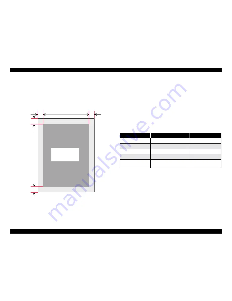
Guaranteed print area:

Entire paper area except for a 4 mm margin at each edge.
(See Figure 1-1, "Guaranteed print Area").

NOTE: The printable area may depend on the printer mode.

Figure 1-1.  Guaranteed print Area

1.2.4  Reliability, Durability, Serviceability

MPBF:

25, 000 sheets min. one-sided printing

Note:
This figure indicates the mean pages until a failure 
requiring part replacement or a failure that the user 
cannot remedy.

MTBF:

3,000 hours (10 month) minimum

Paper Feeding:

See table below.
Applicable conditions for the following figures is using 
standard paper under standard environmental conditions.

*1:

Not including multiple-sheet feed.

*2:

1C indicates 1mm corner fold.

G u a r a n t e e d  

p r i n t   a r e a

4 m m

4 m m

4 m m

4 m m

Table 1-10.  Paper Feed Reliability

Error type

Paper Tray

Lower Cassette Unit

Paper-jam rate

*1

1/2000 max.

Paper misfeed

1/2000 max.

Multiple-sheet feed rate

1/500 max.

Paper creasing

1/1000 max.

Leading edge folded

1/1000 max. for 1C or more.
Less than 1C not included.

*2

Summary of Contents for EPL-5800

Page 1: ...EPSONEPL 5800 A4MonochromeLaserPrinter SEPG99012 SERVICE MANUAL SERVICE MANUAL SERVICE MANUAL SERVICE MANUAL ...

Page 2: ...e contents of this manual However should any errors be detected SEIKO EPSON would greatly appreciate being informed of them The above not withstanding SEIKO EPSON CORPORATION can assume no responsibility for any errors in this manual or the consequences thereof EPSON is a registered trademark of SEIKO EPSON CORPORATION General Notice Other product names used herein are for identification purpose o...

Page 3: ...D REPAIR TECHNICIAN 2 MAKE CERTAIN THAT THE SOURCE VOLTAGES IS THE SAME AS THE RATED VOLTAGE LISTED ON THE SERIAL NUMBER RATING PLATE IF THE EPSON PRODUCT HAS A PRIMARY AC RATING DIFFERENT FROM AVAILABLE POWER SOURCE DO NOT CONNECT IT TO THE POWER SOURCE 3 ALWAYS VERIFY THAT THE EPSON PRODUCT HAS BEEN DISCONNECTED FROM THE POWER SOURCE BEFORE REMOVING OR REPLACING PRINTED CIRCUIT BOARDS AND OR IND...

Page 4: ...ifications of the product CHAPTER 2 OPERATING PRINCIPLES Describes the theory of electrical and mechanical operations of the product CHAPTER 3 TROUBLESHOOTING Provides the step by step procedures for troubleshooting CHAPTER 4 DISASSEMBLY AND ASSEMBLY Describes the step by step procedures for disassembling and assembling the product CHAPTER 5 ADJUSTMENT Provides adjusting procedures CHAPTER 6 MAINT...

Page 5: ...Revision Status Revision Date of Issue Description A January 7 2000 First Release B February 15 2000 Chapter 7 Appendix The parts list is added ...

Page 6: ...C H A P T E R 1 PRODUCTDESCRIPTION ...

Page 7: ...ard interfaces IEEE1284 parallel interface USB interface Windows 2000 supported One Type B interface slot equipped Level 3 supported Euro Symbol supported EnhancedMicroGray installed available only in 600dpi and 300dpi automatically Off at 1200dpi RITech installed available only in 600dpi and 300dpi Automatically switched Off when 1200dpi is selected SOFTWARE FEATURE The following modes and resolu...

Page 8: ... automatic cleaning is carried out Table 1 3 Differences from EPL 5700 Item EPL 5700 EPL 5800 Note Engine speed 8ppm 10ppm Real 1200dpi support x 5ppm when 1200dpi is selected CPU performance R4300 100MHz R4310 133MHz RAM capacity Standard Maximum 4MB 36MB 16MB 256 MB 1 RAM type EDO RAM SIMM SDRAM DIMM Expansion ROM ROM DIMM x 2 ROM DIMM 2 x 1 For Adobe PS 3 kit Serial I F RS232C USB Support USB R...

Page 9: ... 27sec maximum 29sec maximum LGL 19sec maximum 29sec maximum B5 18sec maximum 26sec maximum A5 18sec maximum 24sec maximum Table 1 6 Paper Supply Paper Feed Method Capacity Paper Size Paper Thickness Paper Tray Fixed 150 sheets 1 Standard or custom paper sizes within the following ranges 76 2x127 to 215 9x355 6mm A4 JIS BIDS A5 Letter Government Letter Executive Legal Government Legal F4 Half Lett...

Page 10: ...capacity Face down Max 100 sheets with standard paper immediately after unpacked Face up Max 20 sheets with standard paper immediately after unpacked Switching between face up face down is made by manually operating the lever on the top of the printer Dimensions 387W x 475D x 338 H mm Main unit only Weight Approx 7kg excluding consumables or options Table 1 7 Paper Size Paper Size Paper Size mm in...

Page 11: ...ll non toxic 1 2 2 Process Specification Method Electrophotographic method using dry mono component developing Light source Semiconductor laser Exposure OPC organic photoconductor drum Charging Rotary brush charging method Developing Exposed area development Toner Mono component non magnetic toner Transfer method Roller Transfer Fusing Heat and pressure roller system Density adjustment Bias variab...

Page 12: ...sily Paper with glue staples or clips attached Special inkject paper superfine paper glossy film etc OHP film for color laser printers or photocopiers Sheets already printed on other color or black white laser printers or photocopiers Sheets of paper stuck together NOTE When printing on pre printed papers the paper may not feed correctly due to paper particles adhering to the paper feed roller If ...

Page 13: ...ilure requiring part replacement or a failure that the user cannot remedy MTBF 3 000 hours 10 month minimum Paper Feeding See table below Applicable conditions for the following figures is using standard paper under standard environmental conditions 1 Not including multiple sheet feed 2 1C indicates 1mm corner fold G u a r a n t e e d p r i n t a r e a 4 m m 4 m m 4 m m 4 m m Table 1 10 Paper Feed...

Page 14: ... c d 2 0 mm Sub scan direction a b 1 5 mm See Figure 1 2 Paper Skew Figure 1 2 Paper Skew Durability 5 years or 180 000 sheets whichever comes first Including parts replaced by service technicians See 6 1 3 Maintenance by Service Technicians Serviceability MTTR 30 minutes max Time for service technician to locate and repair a failure Output paper curl height Plain paper 30mm max OHP 20mm max a b c...

Page 15: ...t Surrounding space Keep the space shown in the figures below around the printer to ensure normal printer operation Units mm Figure 1 3 Top View Figure 1 4 Right View NOTE Additional space of 150mm is necessary on the backside of the printer when the Face up tray is installed NOTE Additional space of 125mm is necessary over the printer when the Lower cassette unit is installed 547 D with the top c...

Page 16: ...to 2kv Transient outage DIP 100 at rated voltage 10 for one cycle with normal print quality Electrostatic tolerance Up tp 10 kv No hardware error Up tp 15 kv No component damage Surge current 1 2 cycle 50A max Insulation resistance 10 M Ω min Dielectric strength No breakdown when the following voltages are applied for one minute 100V model AC 1000V Primary to chassis 200V model AC 1500V Primary to...

Page 17: ...effect on human health OSHA Ozone UL478 5th edition Materials SWISS environmental laws not including Cds Table 1 12 Safety Standards Model Name Applicable Standard 100V model UL 1950 3rd CSA 22 2 No 950 200V model TÜV GS EN60950 CCIB Russian Safety Standards Singapore Safety Standards Hong Kong Safety Standards IEC950 Table 1 13 Safety Regulations Laser Radiation Model Name Applicable Standard 100...

Page 18: ...es each way Direction of vibrations 3 directions Vibration time 60 minutes in X Y Z directions total 180 minutes Table 1 15 Consumable Specifications Name Contents Life 1 Weight Developer and Toner cartridge Developer Black one component non magnetic toner Average 6 000 sheets approx 0 5 kg Photoconductor unit OPC drum organic photoconductive conductor Charger Average 20 000sheets approx 0 3 kg Ta...

Page 19: ... 1 3 External Appearance and Parts Name The following illustrations are top right and left and back views of the unit Figure 1 5 Top View Figure 1 6 Left View Figure 1 7 Right View Top Cover Paper Feed Switchover Lever Operation Panel Paper Tray Right Cover Option Cover ...

Page 20: ...ounted on ROM DIMM board Expansion ROM one ROM DIMM slot for PS option Host I F Parallel IEEE1284 compliant bidirectional B type connector Compatibility Nibble ECP Serial USB Option Type B slot one slot Control Panel 4 switches 6 LED Miscellaneous Embeded engine controller Installed emulations PCLXL PCL5e GL 2 FX ESCP2 1239X ESC Page 1 PostScrtipt3 2 1 The IES does not support ESC Page Only the ES...

Page 21: ...o the market destination The settings are made with jumpers and must thus be set at the factory JUMPER SETTING Packaged resistance RJ2 RJ3 RJ5 RJ7 RJ10 RJ12 RJ13 Unpackaged resistance RJ1 RJ4 RJ6 RJ8 RJ9 RJ11 RJ14 Packaged JP7 Unpackaged SWD1 JP6 JP7 1 2 side DESTINATION SETTINGS A4 LETTER SELECTION For North and South America 120V model Letter setting Other destinations A4 setting ...

Page 22: ...AGE 04 PCLXL 2 MDL 3 CLS PRINTER DES 4 MFG MDL CID of Device ID are re definable this must not be included in the manual And CID field does not respond with the default value but responds with the defined character string only when redefined Device ID when redefined is as follows xxxxx is user defined character string 1 MFG xxxxx CMD PJL EJL ESCPL2 PRPXL24 01 PCL HPGL2 01 ESCPAGE 04 PCLXL 2 MDL xx...

Page 23: ...conforms to 1 4 3 1 Parallel Interface 1 4 3 3 Type B Interface EPL 5800 is equipped with one Type B option I F slot as standard Main System Type MTP1200dpi PW10200dt1200dpi PRG rev AP500ma SPD0fast D4 ROM version Printer Name Factory default setting is the same as one of Product Name Product Name EPL 5800 Emulation Type See the Table 1 17 Entity Type See the Table 1 17 C A U T I O N The USB ID is...

Page 24: ...EPSONPAGE4 EPSONPCL5 EPSONLQ2 EPSONHPGL2 EPSONPRPXL24 When Emulation is fixed the following Entity Type will be returned Default Emulation EPSONPAGE4 NOTE The number of entity types returned to the host depends on the specification of Type B interface Emulation Type If Emulation is set to Auto If PS3 is OFF AUTO Emulation Type 1 2 3 If PS3 is ON EJL POSTSCRIPT 00 other Emulation Type 1 2 3 If Emul...

Page 25: ...NOTE For Taiwan and China the panel sheet is written in each language 1 2 3 6 5 4 10 9 8 7 Table 1 18 Buttons and LEDs No Name Note 1 On line LED Color Green 2 Data LED Color Yellow 3 Continue LED Color Red 4 Paper LED Color Yellow 5 Toner LED Color Yellow 6 Memory LED Color Yellow 7 On Line switch 8 Form Feed switch 9 Continue switch 10 Alternate switch ...

Page 26: ... FX Font Sample I239X Font Sample Emulation Menu Parallel Auto LJ4 ESCP2 FX I239X PS3 1 GL2 USB Auto LJ4 ESCP2 FX I239X PS3 1 GL2 AUX 3 Auto LJ4 ESCP2 FX I239X PS3 1 GL2 Printing Menu Paper Source Auto MP LC 4 Page Size A4 5 A5 B5 LT 5 HLT LGL GLT GLG EXE F4 MON C10 DL C5 C6 IB5 CTM Wide A4 Off On Orientation Port Land Copies 1 999 Quantity 6 1 999 Manual Feed Off On Resolution 600 1200 7 300 Dot ...

Page 27: ...and printing on the Status Sheet are immediately reflected but become valid after warm boot or at power on again 12 Appears only when the optional Type B interface card is installed Network card configurations cannot be made from the printer side Use the utility that comes with each card 13 Display only when Type B Level 3 card is installed This value cannot be changed and always set to No Functio...

Page 28: ... Europe PcTk437 PcEur858 Pc1004 WiAnsi WiE Europe WiTurkish WiBALT DeskTop PSText VeInternati VeUS MsPublishin Math 8 PsMath VeMath PiFont Legal UK ANSI ASCII Swedis2 Italian Spanish German Norweg1 French2 Windows McText PcIcelandic PcLt774 PcTurk1 PcPortugues PcET850 PcTurk2 PcCanFrench PcS1437 PcNordic 8859 3 ISO 8859 4 ISO WinBaltic WiEstonian WiLatvian Mazowia CodeMJK BpBRASCII BpAbicomp PcGk4...

Page 29: ...n Table 1 20 Function Setting 2 Menu Item Value ESCP2 Menu Font Courier Prestige Roman Sans serif Roman T Orator S Sans H Script OCR A OCR B Pitch 10cpi 12cpi 15cpi Prop Condensed Off On T Margin 0 40 0 50 1 50 inch 0 05 inch increments Text 1 62 6 66 7 available Max 81 Lines CGTable PcUSA Italic PcMultilin PcPortugue PcCanFrenc PcNordic PcTurkish2 PcIceLandic PcE Europe BpBRASCII BpAbicomp Roman ...

Page 30: ...s are automatically made as follows FX Menu Font Courier Prestige Roman Sans serif Script Orator S OCR A OCR B Pitch 10cpi 12cpi 15cpi Prop Condensed Off On T Margin 0 40 0 50 1 50 inch 0 05 inch increments Text 1 62 8 66 9 available Max 81 Lines CGTable PcUSA Italic PcMultilin PcPortugue PcCanFrenc PcNordic PcTurkish2 PcIcelandic PcE Europe BpBRASCII BpAbicomp Roman 8 PcEur88 ISO Latin1 8859 15 I...

Page 31: ...ion B Product Description Control Panel 33 Font Source Resident Font Number 0 Due to this to print by this symbol set a font must be selected for which the Font Source and Font Number Value are supported by this symbol set ...

Page 32: ...n Stop Toner Out error occurs when the measurement of Toner counter reaches to the level where Toner Out error occurs PAPER TYPE Specifies the paper type loaded in the MP Tray Normal Normal paper Thick W Thick paper Thick N Thick and narrow paper like an envelop Transprnc OHP sheets MP TYPE LC TYPE Specifies the paper type for MP Tray or LC When Paper Source Auto MP Type and LC Type is used to sel...

Page 33: ...ault setting When use a fixed interface set On only for the interface that to be used Changes to the interface setting will be effective after the Reset All is performed or the power is turned on again If Off is set to all interfaces they are reset to On after the Reset All is performed or the power is turned on again It is not allowed to set Off to all interfaces On X Off Table 1 23 Interface Set...

Page 34: ...sage Error Message Warning Message and Service Call Error Message Status Message is displayed only when there are no error or during the initialization No two Status Messages displayed at the same time and Error Message is displayed in the priority order Refer to the tables on following pages for each error indication ...

Page 35: ...indicates the printer is performing self check 5 The printer is now ready to print During the sequence above if any service call error has detected corresponding error message is indicated Status Messages in LCD Equipped Models Paper LED Toner LED Memory LED Online LED Data LED Continue LED Classification Service Req effff Refer to 1 6 Service Call Errors Status System Check Status Reset All Statu...

Page 36: ...rmal data transfer Status Write Error ROM A Error Collate was disabled Warning Check Paper Size Warning Image Optimum Warning Check Paper Type Warning Format Error ROM A No indication EJL status will be supported Warning Need memory Warning Form Feed Status Warning Up Status Toner Low Warning Offline Online LED goes off Status Standby Status Ready or Status On Off Flashing Table 1 24 Printer Messa...

Page 37: ...ED Condition All LED on 0 8 sec All LED off 0 2 sec Respective LED on specified by error code 0 8 sec All LED off 0 2 sec This sequence is repeated in 2 sec interval Refer to the following Table 1 25 and Table 1 26 for details Solution Turn off the power and back on If an error still remains see the indicated error code to check and replace the concerning unit ...

Page 38: ...Code Explanation Paper LED Toner LED Memory LED Online LED Data LED Continue Lamp C0017 CPU Error Undefined interruption occurred C0081 CPU Error TLB revising exception C0082 CPU Error TLB mistake exception Load Fetch C0083 CPU Error TLB mistake exception Store C0084 CPU Error Address error exception Load Fetch C0085 CPU Error Address error exception Store C0086 CPU Error Bus error exception Store...

Page 39: ...enough for minimum stack etc C1002 Standard RAM error Not enough for standard size etc C1003 Option RAM error C1100 ROM checksum error bit0 15 font C1101 ROM checksum error bit16 31 font C1120 ROM checksum error bit0 7 program C1121 ROM checksum error bit8 15 program C1122 ROM checksum error bit16 23 program C1123 ROM checksum error bit24 31 program C1170 Option font ROM checksum error C1180 Optio...

Page 40: ...0 EEPROM writing error C1210 EEPROM writing limit C1400 Engine initialization error C1999 Other hardware error C2000 Software error On Off Table 1 26 Service Call Error Controller Related Error Code Explanation Paper LED Toner LED Memory LED Online LED Data LED Continue Lamp ...

Page 41: ...on of common functional environment and I F specific functional environment and set the factory default values UPDATE PROGRAM ROM This operation activates the Code ROM DIMM update function 1 By executing the operation the printer starts normal power on sequence Keep depressed all buttons until Paper Toner and Memory LEDs are turned on after completing RAM check 2 Next release all the buttons and O...

Page 42: ...e memory EEPROM If the printer is powered off during the process of writing to non volatile memory the writing operation to the non volatile memory cannot be guaranteed And therefore the next time the printer is powered on or the Reset All is carried out panel settings may be initialized or a service call error may occur The non volatile memory saves the function settings and the following cases a...

Page 43: ...C H A P T E R 2 OPERATINGPRINCIPLES ...

Page 44: ...he main motor M1 is transmitted to the paper feed roller via the paper feed clutch one way clutch and the paper feed roller rotates At the same time the push down cam rotates and it lifts the tray lifting plate Paper on the tray is carried into the printer by the paper feed roller Separation pad method is used in order to separate each paper and prevent feeding the second paper together Since ther...

Page 45: ...ng gear Paper feed method is the same as for multi paper feed tray As separation method the separation pad method is used for the multi paper feed tray but the separator claw is used for the second paper feed unit The separator claw is the method that uses elasticity between the separator installed at the paper fed cassette and the paper Only one sheet of paper is fed by one paper feed operation T...

Page 46: ... on the second paper feed unit When the cassette for each paper size is inserted the switch presser on the right side of each cassette pushes the lever according to the paper size and it turns the cassette type sensor ON This switch is the three consecutive switch and the printer distinguishes the cassette type paper size by ON OFF combination of three switches Figure 2 4 Cassette Type Sensor Mech...

Page 47: ...l because of direct charging to the OPC drum Electric potential on the surface of OPC drum after charging is about 800V A rotation brush charging brush rotates when drive from the main motor M1 is transmitted to the gear of the rotation brush charging brush Pre charging film takes a pre charge before the rotation brush charging brush takes a charge in order to improve efficiency of charging Figure...

Page 48: ...ain motor M1 starts the paper feeding operation When the specified period of time passes after the end of fed paper turns the paper feed sensor ON TOD signal the main control board sends the VIDEO signal to the print head and printing starts When moving on from the first line to the second line the print starting position is shifted down by delaying the VIDEO signal sending time MAIN SCANNING DIRE...

Page 49: ... which corresponds to the paper size to the engine controller The main control board determines the printing start position by TOD signal sub scanning direction and the HSYNC signal sent by the engine controller The print head starts laser exposure when it receives the VIDEO signal Figure 2 7 Printable Area Printable Area VIDEO HSYNC TOD 4mm 4mm VIDEO ...

Page 50: ...tes the toner hopper inside and sends toner to the toner sending roller 3 Toner sending roller Transfers toner to the sleeve roller 4 Sleeve roller Rotates the resin sleeve 5 Resin sleeve Transfers toner to the surface of the OPC drum surface 6 Photoconductor OPC drum Creates the latent image on the surface by the laser beam Develops the image by the resin sleeve and carries the developed image to...

Page 51: ...nciples Operating Principles of Mechanism 53 9 Development blade voltage terminal VBL DC 590V 10 Development voltage terminal VB DC 340V 11 Under development seal terminal Vss DC 340V Table 2 2 Parts of Developing Mechanism No Name Function ...

Page 52: ...r method has low rate of ozone occurrence by corona discharge and chances for dislocating the transferred image is very small because the paper passes between the drum and the transfer roller all through during printing The reversed bias is charged on the transfer roller when cleaning the transfer roller before printing Leftover electric potential on the paper is removed by the discharge needle Fi...

Page 53: ...tor detected temperature the heater lamp H1 is turned ON light on and OFF light off by the heater lamp ON OFF signal which is output by the IC1A 55 and controls the temperature of the fusing components When the heater lamp is not turned OFF even though the thermistor detects abnormal high temperature when the surface temperature of the fusing heat roller exceeds 210 C the output from IC 79 is chan...

Page 54: ...ys ON until the temperature of the hear roller reaches about 155 C Then the following temperature controls are performed Temperature control mode 1 Controls temperature during printing as 155 C and temperature in standby as 115 C After this mode continues for 45 seconds it shifts to the mode 2 Temperature control mode 2 After this mode continues for 208 seconds it shifts to the mode 3 Printing tem...

Page 55: ... eject or to the face down eject is switched The paper eject switching lever is located at the paper eject Figure 2 14 Paper Eject Mechanism FACE DOWN EJECT Paper is ejected to the face down tray which is located on the top of the printer FACE UP EJECT Paper is ejected to the optional face up tray Face up eject is available even without optional face up tray Face up Eject Face down Eject Paper Eje...

Page 56: ...C H A P T E R 3 TROUBLESHOOTING ...

Page 57: ...sensor PS1 is not turned ON within about 2 1 seconds at 1200dpi within about 13 58 sec after the multi paper feed tray starts feeding paper in other words the paper feed roller starts rotating by turning the paper feed solenoid ON within about 2 35 seconds at 1200dpi within about 4 7 sec after the second paper feed unit starts feeding paper 2 The paper feed sensor PS1 is not turned OFF within abou...

Page 58: ...cond paper feed solenoid SL21 Yes Is recommended paper used No Ask the user to use the recommended paper Yes Is paper bent wrinkle or wet Yes Replace the paper and tell the user how to keep paper No Is the paper feed roller deformed Or is it worn out by friction or is there any dirt Yes Replace the paper feed roller Replace the second paper feed roller No Does the lever of the paper feed sensor PS...

Page 59: ...otor is turned ON 2 Motor lock signal is turned OFF for 0 1 sec continuously ABNORMAL FAN MOTOR This error is detected in the following case 1 Motor lock signal is detected as H for 2 0 sec continuously after the fan motor is turned ON At normal rotation the motor lock signal indicates L ABNORMAL FUSING 1 If in any condition the thermistor detects that the temperature exceeds 220 C for 50msec it d...

Page 60: ...tem Remedy Cooling Fan Motor M2 does not rotate Replace the cooling fan motor M2 Replace the main control board Table 3 8 Troubleshooting for the Abnormal Fusing Check Item Remedy Is the fusing unit warmed up Yes Replace the thermistor TH1 or the fusing unit Replace the main control board Replace the power unit PU1 No Is there continuity between Pin 1 and Pin 3 of the connector of the fusing unit ...

Page 61: ...it 67 8mm Backup Roller φ 21 6mm Pitch mm Abnormal Image Table 3 11 Print Quality Problems 2 Symptom Possible Cause Solution All White No toner cartridge Install the toner cartridge No toner in the toner cartridge Replace the toner cartridge No drum cartridge Install the drum cartridge Defective OPC drum Replace the OPC drum Abnormal laser emission Replace the print head Replace the high voltage u...

Page 62: ...ain control board Foggy background Defective developing bias Replace the high voltage unit HV1 Replace the main control board OPC drum is at the end of life Replace the drum cartridge Table 3 11 Print Quality Problems 2 Symptom Possible Cause Solution 0951o226 0951o214 0951o218 White line Black line There is scar or damage on the OPC drum Replace the OPC drum Defective print head Replace the print...

Page 63: ...C H A P T E R 4 DISASSEMBLYANDASSEMBLY ...

Page 64: ...inserting or removing a connectors be sure to do so holding the connector housing Never insert or remove connectors holding the wiring cord it may result in a loose connection Use the specified rated fuses In order to ensure the electric conduction install the earth wire and the earth plate correctly and firmly After removing the out teethed washers make sure to re install them Do not replace them...

Page 65: ...void touching IC terminals and patterns C A U T I O N Avoid direct IC check by the tester Determine OK NG by checking the connector on the board Be sure to avoid any short between IC terminals caused by metallic tools If touching the elements on the board is unavoidable be sure to perform body earth C A U T I O N For transporting and keeping be sure to use specified boxes When keeping the printer ...

Page 66: ...Cartridge Supplied by a consumer None About 6 000 sheets About 4 800 sheets Toner Cartridge Packaged None About 3 000 sheets About 2 400 sheets Transfer Roller A and C environment in the Figure 4 1 None About 135 000 sheets About 80 000 sheets Transfer Roller B environment in the Figure 4 1 None About 100 000 sheets About 50 000 sheets Fusing Unit None About 50 000 sheets Paper feed roller When pa...

Page 67: ...Lamp H1 Heat Roller Thermostat TS1 Thermistor TH1 Fusing Separation Claw Paper Feed Unit Front Cover Front Cover Transferring Paper Feed Sensor PS1 Paper Feed Roller Cover Paper Empty Sensor PE1 Paper Feed Solenoid SL1 Main Motor Assembly Power Supply Unit PU1 Interlock Switch S2 Control Panel High Voltage Unit HV1 Left Cover 4 2 1 4 2 5 4 2 4 4 2 3 4 2 7 4 2 16 4 2 17 4 2 9 4 2 12 4 2 13 4 2 14 4...

Page 68: ...pen the top cover as full open 2 Take out the toner cartridge 3 Take out the drum cartridge 4 2 2 Paper Feed Roller Replacement 1 Open the paper feed roller cover and remove the paper feed roller one screw NOTE When installing the paper feed roller tighten the screw after making sure the pin on the back of the roller goes in the shaft hole Figure 4 5 Paper Feed Roller Replacement Toner Cartridge D...

Page 69: ... the transfer roller to the transfer roller holder of the printer and set the bearing lever to the top Figure 4 7 Installing the Transfer Roller 5 Install the transfer front cover two screws C A U T I O N Since the life span of the transfer roller and fusing unit are the same if you need to replace the transfer roller because of worn out etc make sure to replace the fusing unit as well Do not touc...

Page 70: ...he paper empty sensor PE1 and pull out the connector Figure 4 8 Paper Empty Sensor PE1 Removal 4 2 5 Right Cover Removal 1 Remove the right cover two screws two hooks NOTE When installing the right cover insert two hooks at the bottom of the right cover to the frame Figure 4 9 Right Cover Removal 4121s073 Paper Feed Roller Cover Paper Empty Sensor 4121s045 ...

Page 71: ... 1 Remove the control panel two screws Figure 4 10 Control Panel Removal 4 2 7 Main Control Board PWB P Removal 1 Remove all connectors on the main control board PWB P twelve connectors and remover the main control board PWB P ten screws Figure 4 11 Main Control Board PWB P Removal 4121s084 4121s046 3501 ...

Page 72: ...the paper empty sensor when removing the front cover When installing the left cover insert the hooks at the bottom of the cover to the frame Figure 4 12 Left Cover and Front Cover Removal 4 2 9 Paper Feed Solenoid SL1 Removal 1 Remove the right cover the left cover and the front cover 2 Close the top cover and turn it down 90 to the back Figure 4 13 Paper Feed Solenoid SL1 Removal 1 4121s047 3504 ...

Page 73: ...over Removal 1 Remove the right cover and the left cover 2 Remove the top cover two hooks Figure 4 15 Top Cover Removal 4121s050 4121s075 When removing the solenoid pull the right side of the paper feed unit endways and remove it while shifting the whole unit to the right When installing the unit make sure that the screw in part of the unit goes in the left resinous frame Top View 4121s074 Paper F...

Page 74: ...oval 1 Remove the rear cover six screws one connector 2 Remove the top cover two hooks Figure 4 16 Rear Cover Removal 4 2 12 Cooling Fan Removal 1 Remove the rear cover 2 Remove the cooling fan three screws Figure 4 17 Cooling Fan Removal 4109s52 1112 3501 3704 3501 3501 3704 3501 3501 4109s53 3704 ...

Page 75: ...move the right cover the left cover and the rear cover 2 Remove the fusing unit three screws three connectors Figure 4 19 Fusing Unit Removal NOTE If you need to disassemble the fusing unit because of image quality problems and defective components follow the instruction in Fusing Unit Disassembly on page 78 4121s054 C A U T I O N The life span of the transfer roller and fusing unit are the same S...

Page 76: ...rate the fixation unit Figure 4 20 Fusing Unit Disassembly 3 Remove the backup roller 4 Remove the fixation front guide board 1 Shift the fixation front guide board to the left 2 Remove the right side of the fixation front guide 3 Remove the left side of the fixation front guide Figure 4 21 Backup Roller and Front Fusing Guide Removal 4121s057 3704 4121s058 1 2 3 Backup Roller Front Fusing Guide ...

Page 77: ... to 2 direction and pull the roller out toward 3 direction Figure 4 23 Drive Gear Removal C A U T I O N Do not touch the glass of the lamp with bare hands When installing the heater lamp install it as the voltage indicator faces the gear side 4121s059 Voltage Indicator 3704 1305 Heater Lamp C A U T I O N To avoid scratching the heat roller surface by the fusing separation claw when removing or ins...

Page 78: ...he figure 1 of the Figure 4 24 12 Remove the thermostat TS1 two screws Figure 4 24 Thermistor and Thermostat Removal 4 2 16 Interlock Switch S2 Removal 1 Remove the right cover the left cover and the rear cover 2 Remove the interlock switch S2 one screw two connectors Figure 4 25 Interlock Switch S2 Removal Figure 1 Back of the Fusing Unit 4121s061 Thermistor Fusing Separate Claw 4 Thermostat 3704...

Page 79: ... seven screws NOTE When installing the print head PH1 install it with the shutter open Figure 4 26 Print Head Unit PH Removal 4 2 18 Power Unit PU1 Paper Feed Sensor PS1 Removal 1 Remove the right cover the left cover and the front cover 2 Pull out PJ7 from the main control board and remove the harness from the cold holder 3 Remove the power supply unit PU1 four screws two connectors Figure 4 27 P...

Page 80: ...over 2 Remove the power supply unit 3 Remove the high voltage unit HV1 three screws one connector NOTE When installing the high voltage unit HV1 be careful at the following points Install the earth plate at the rear of the high voltage unit as shown in the Figure 1 in the Figure 4 29 Make sure all the contact points four points are contacted Figure 4 29 High Voltage Unit HV1 Removal 4121s065 4121s...

Page 81: ...4 30 1 Lift the tab of the paper feed roller 2 Shift the paper feed roller to the right 3 Remove the paper feed roller 3 Install a new paper feed roller by reversing the procedure of step 2 Figure 4 30 Second Paper Feed Roller Replacement 4 2 21 Second Paper Feed Unit Removal 1 Remove the black cover one screw two picks 2 Remove the actuator Figure 4 31 Actuator Removal 4121s067 Figure 1 Paper Fee...

Page 82: ...he second paper feed unit Figure 4 32 Paper Feed Unit Removal 4 2 22 Relay Board PWB A Removal 1 Remove the cover one screw two connectors 2 Remove the relay board PWB A two screws Figure 4 33 Relay Board PWB A Removal 4121s069 3504 3704 3704 3704 3704 3704 4121s070 3501 3501 Relay Board ...

Page 83: ...itch SW21 Figure 4 34 Second Paper Size Detection Switch SW21 Removal 4 2 24 Second Paper Feed Solenoid SL21 Removal 1 Remove the cover one screw 2 Remove the harness from the wire saddle and remove the second paper feed solenoid SL21 one screw one connector Figure 4 35 Second Paper Feed Solenoid SL21 Removal 4121s071 4121s072 3501 Wire Saddle Second Paper Feed Solenoid ...

Page 84: ...C H A P T E R 5 ADJUSTMENT ...

Page 85: ...NTING 1 Remove the right cover and prepare VR1 on the main control board ready for adjustment 2 If you rotate VR1 on the main control board clockwise d gets larger If you rotate VR1 on the main control board counterclockwise d gets smaller Figure 5 1 Print Start Position Adjustment ADJUSTMENT BY VOLTAGE CHANGE 1 With the power ON put terminal of the tester on VR1 and terminal on the frame GND 2 Ad...

Page 86: ...e position adjustment of interlock switch S2 by the following procedure 1 Open the top cover and remove the left cover the right cover and the front cover 2 Loosen the screw fixing interlock switch S2 and close the top cover completely 3 Move the interlock switch S2 up and down and tighten the screw where the switch turns ON Figure 5 2 Interlock Switch Position Adjustment 4121s082 S2 ...

Page 87: ... SETUP 1 Insert the supplied program diskette labeled as Disk 1 into a floppy disk drive on the PC and execute the program SETUP EXE 2 Follow the setup instruction displayed on the PC replace the floppy disk to Disk 2 when you are instructed to do so by the setup program 3 When the setup is completed you can start the program by selecting it from the Program menu PROGRAM OPERATION 1 When you execu...

Page 88: ... verify it with the following procedure 1 After executing the program and selecting the printer click on Verify USB ID radio button 2 When you clicking on OK button the program prints the status sheet Then confirm that the USB ID value printed on the status sheet is the same as the one you have confirmed when you input it C H E C K P O I N T USB ID is 18 digit value and the program automatically g...

Page 89: ...C H A P T E R 6 MAINTENANCE ...

Page 90: ...s alcohol Table 6 2 Maintenance of Consumables Maintenance Item Timing Method Developer cartridge Replace after printing approx 6 000 sheets Follow the procedure below to replace the Developer cartridge 1 Press the open button and open the top cover 2 Grasp the handles on the Developer cartridge and pull off the cartridge from the unit 3 Hold the new Developer cartridge and shake it from side to s...

Page 91: ...lowing maintenance must be undertaken by a qualified service technician Table 6 3 User Maintenance by Service Technicians Maintenance Item Timing Transfer roller Clean when a problem occurs Replace after printing 50 000 sheets Fusing unit Clean when a problem occurs Replace after printing 50 000 sheets ...

Page 92: ...C H A P T E R 7 APPENDIX ...

Page 93: ... 1 Connector List Connector Description Pin Table C361MAIN BOARD CN1 CODE DIMM 72 Table 7 2 CN2 ROM DIMM 72 Table 7 2 CN3 Parallel I F 36 Table 7 3 CN4 Control Panel 26 Table 7 4 CN5 Type B I F Slot 36 Table 7 5 CN6 Not used CN7 SDRAM DIMM 168 Table 7 6 CN8 USB I F 4 Table 7 7 CN9 Not used CN10 Not used CN202 Thermistor 2 CN203 Solenoid 4 CN204 HVPS 11 CN205 Optical unit Laser diode 8 CN206 Main m...

Page 94: ...D Ground 70 NC Not used Table 7 1 Connector List Connector Description Pin Table Table 7 3 Connector CN3 Pin No Signal I O Description 1 STB I STROBE signal 2 9 DATA1 DATA8 I O Data signal Bit 1 to 8 10 ACK O ACKnowledge signal 11 BUSY O BUSY signal 12 PE O Paper End signal 13 SELOT O Always HIGH 14 AUTO I 1284 mode request signal 15 NC Not used 16 GND Ground 17 CG Chassis ground 18 NC Not used 19...

Page 95: ...t used Table 7 4 Connector CN4 Pin No Signal I O Description 1 6 VCC 5V 19 24 GND Ground 10 NC Not used Table 7 6 Connector CN7 Pin No Signal I O Description 33 38 117 121 123 126 A0 A12 O Address signal 132 A13 Not used 39 122 BA0 BA1 O Bank select address signal 2 5 7 11 13 17 19 20 55 58 60 65 67 69 72 74 77 86 89 91 95 97 101 103 104 139 142 144 149 151 153 156 158 161 DQ0 DQ63 I O Data bus 30...

Page 96: ...108 109 134 137 145 147 164 NC Not used 6 18 26 40 41 49 59 73 84 90 102 110 12 4 133 143 157 168 VCC 3 3V 1 12 23 32 43 54 64 68 78 85 96 107 116 127 138 148 152 162 VSS Ground Table 7 7 Connector CN8 Pin No Signal I O Description 1 POWER 5V 2 D I O Data 3 D I O Data 4 GND Ground Table 7 6 Connector CN7 Pin No Signal I O Description ...

Page 97: ...EPSON EPL 5800 Revision B Appendix Component Layout 99 7 3 Component Layout The figure below shows the component layout of the C361MAIN Board Figure 7 2 Component Layout C361MAIN BOARD CN212 ...

Page 98: ...PL 5800 Revision B Appendix Circuit Schematics 100 7 4 Circuit Schematics The circuit schematics of C361MAIN board is provided on the following pages C361MAIN BOARD No 1 C361MAIN BOARD No 2 C361MAIN BOARD No 3 ...

Page 99: ......

Page 100: ......

Page 101: ......

Page 102: ...D ASSY MAIN 2 01 EARTH GROUND 2 02 TORSION SPRING 2 03 MEMBER 2 04 HOLDER 2 05 LEVER 2 06 SHOULDER SCREW 2 07 TORSION SPRING 2 08 COVER 2 09 ROLLER 2 10 GEAR ASSY 2 11 GUIDE 2 12 GUIDE 3 01 PAPER PICK UNIT 3 02 ROLLER 3 03 SEPARETOR PAD 3 04 SOLENOID 4 01 ACTUATOR 4 02 PHOTO INTERRUPTER PS3 4 03 BUSHING 4 04 FUSING ROLLER RR 4 05 BUSHING 4 06 TUBE LAMP H1 230V 4 07 FUSING ROLLER 4 08 PRESSURE SPRI...

Page 103: ...ROUND 6 10 EARTH GROUND 7 01 POWER SUPPLY 7 02 FERRITE CORE 7 03 GUIDE 7 04 PRINT HEAD UNIT 7 05 GUIDE ASSY 7 06 POWER CABLE 0601 PIN Table 7 8 Service Parts List Main Unit Ref No Parts Name 1305 SCREW 1308 SCREW 2514 SCREW 2903 SCREW 3501 TAPPING SCREW 3541 TAPPING SCREW 3544 TAPPING SCREW 3704 TAPPING SCREW 3727 TAPPING SCREW 3730 TAPPING SCREW 3907 TAPPING SCREW 3923 TAPPING SCREW 4012 TAPPING ...

Page 104: ... 8 09 BUSHING 8 10 GEAR 15T 8 11 GEAR 26 32T 8 12 TENSION SPRING 8 13 GEAR 34T 8 14 SOLENOID 8 15 GUIDE 8 16 SWITCH SW21 8 17 COVER 9 01 CASSETTE ASSY A4 9 02 WIRING SADDLE 5 2H 9 03 WIRING SADDLE 5 2H 9 04 EDGE COVER 8 5H 9 05 CABLE TIE 0509 PIN 3501 TAPPING SCREW 3504 TAPPING SCREW 3704 TAPPING SCREW 3709 TAPPING SCREW 3906 TAPPING SCREW 9107 RETAINING RING 9112 RETAINING RING Table 7 9 Service ...

Page 105: ... View Diagrams The exploded view diagrams are provided on the following pages Housing components Paper Eject mechanism Paper supply mechanism Fusing unit Main drive Transfer unit Frame Electrical components Option Lower Paper Cassette Unit 1 Option Lower Paper Cassette Unit 2 ...

Page 106: ...G 3541 3541 3730 3727 4012 3544 04 03 01 06 05 08 09 02 16 11 10 12 13 15 450 The parts to which no reference number is assigned will not be available as after sale service parts FOR EPL 5800 NO 1 Rev 01 10185 ...

Page 107: ...2 PAPER EXIT SECTION 3704 3727 3704 3727 02 03 04 05 06 01 06 06 07 07 06 08 12 12 09 11 10 09 FOR EPL 5800 NO 2 Rev 01 10185 ...

Page 108: ...3 PAPER TAKE UP SECTION 0601 1308 9109 3727 3727 3541 3727 3541 3704 SL1 01 03 02 04 FOR EPL 5800 NO 3 Rev 01 10185 ...

Page 109: ...4 FUSING UNIT 3727 PS3 3923 1305 1305 3923 3541 1305 3704 1305 3704 H1 TS1 TH1 3727 3541 01 04 05 06 07 08 09 09 08 08 09 08 09 10 11 12 13 02 03 03 FOR EPL 5800 NO 4 Rev 01 10185 ...

Page 110: ...5 DRIVE TRANSFER UNIT M1 3704 3544 9105 3727 HV1 PS1 3907 3727 07 08 10 11 09 02 01 04 03 05 06 06 FOR EPL 5800 NO 5 Rev 01 10185 ...

Page 111: ... 3544 3544 2903 3544 3727 3544 3544 1305 S2 PE1 3544 3544 05 07 06 02 01 03 06 04 10 08 200 The parts to which no reference number is assigned will not be available as after sale service parts FOR EPL 5800 NO 6 Rev 01 10185 ...

Page 112: ...AL COMPONENTS PU1 1305 3544 3541 3541 3544 3704 3501 2514 8302 03 01 05 04 FOR EPL 5800 NO 7 Rev 01 10185 06 The parts to which no reference number is assigned will not be available as after sale service parts 02 ...

Page 113: ... 3501 3501 3704 3704 3704 3704 9112 0509 3504 PWB A SW21 SL21 3704 3704 01 02 03 04 05 06 08 07 06 09 02 03 10 11 12 13 14 16 15 15 17 02 02 The parts to which no reference number is assigned will not be available as after sale service parts FOR EPL 5800 OPTION NO 1 Rev 01 10187 ...

Page 114: ...9 2ND PAPER TAKE UP B OPTION 3906 3704 3709 3704 3704 01 05 04 02 03 FOR EPL 5800 OPTION NO 2 Rev 01 10187 ...

Reviews: