


Installation Guide
53
Installing the Control Pad
Installation Procedure
See the following for the Control Pad installation location.
s
"Control Pad installation location"
s
"When installing the Control Pad"
a
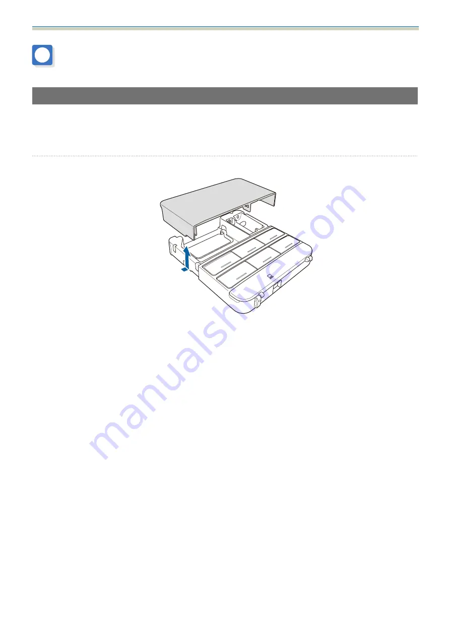
Remove the cable cover
Installation Guide
53
Installing the Control Pad
Installation Procedure
See the following for the Control Pad installation location.
s
"Control Pad installation location"
s
"When installing the Control Pad"
a
Remove the cable cover


