background image

10

epoke

®

SKE8-12-15-20
GB-0305.1

2.2.4 Metering system

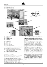
1

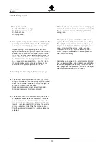
The Epoke principle
A - Impellor shaft with springs 
B - Delivery roller with cams
C - Rubber base
D - Spring base

2

The impellor shaft pulverizes all lumps, distributes the
spreading material in the whole  length of the hopper,
and ensures constant supply  to the delivery roller.

Impellor springs: When replacing defect impellor
springs, the flat side is to point to the front  in working
direction and be placed in two  spirals, which start in
the centre, whereby the  material is lead towards the
centre. Start with  no. 1 in the middle. Turn the tube
1/4 turn  forward in the working direction, mount pair
no.  2 equally on each side of no. 1. Turn 1/4 turn in
the working direction, mount pair no. 3 equally  on
each side of the previously mounted pair etc.

3

Possibility for demounting defect impellor springs.

4

The delivery roller is provided with cams (A)  which
bring the material through the spring  adjusted rubber
base. The cams are available in  different designs for
all types of material and  dosages.
Great and many cams: Great amount (sand etc).
Small and less cams: Small amount (salt).

5

The delivery cams: If the cams are worn, they are  to
be replaced. If the screws are rustbound, the  cams
can be blasted with a hammer, and the screws  be
loosened with tongs. To ease a replacement of  cams
later, it is recommended to fill in approx.  1/4 l waste
oil into the delivery roller. This  has not been done
from the works out of regard  for the oil waste during
shipment.

6

The rubber bases are jammed under the clamping  iron
and can be turned and worn on all edges provided that
they are turned in time, see also description of the
spring base.

7

The spring base presses the bottom rubber base
against the cams of the delivery roller,  regulated by
the spring base adjustment. Defect  springs by wea-
ring are to be replaced. When the  spring base is
open, all points of the springs  are to be in line. 
The spring base stop is adjustable and placed in
order to stop the movement of the spring base for
max. material quantity.

8

Spring base adjustment: The adjustment is obtained
by the pressure of the bottom rubber base with diffe-
rent strength against the delivery roller by means of
the spring base. The pressure is varied by the adjust-
ment handle at the rear of the spreader.

Summary of Contents for SKE Series

Page 1: ...ber here Type Year Ident no Valid from ident no SKE 8 10010200 SKE 12 10030200 SKE 15 10040200 SKE 20 10050200 Published and printed by Epoke A S Documentation department Changes of technical details...

Page 2: ......

Page 3: ...2 1 3 4 Safety during cleaning repairs and maintenance 6 2 1 3 5 Suggestions for a user guide 7 2 1 11 Lubricating grease 7 2 2 Product descriptions 2 2 0 1 Machine overview 8 2 2 1 Product descripti...

Page 4: ...be trained and instructed If necessary this can be implemented through the manufacturer supplier as desired by the purchaser user of the spreader Training abroad is carried out by the local dealers M...

Page 5: ...000 SKE20 10050200 2000 1 4 Country of origin Denmark 1 5 CE mark CE mark is placed on the machine sign 1 6 EU certificate of conformity The above spreader has been manufactured in accordance with the...

Page 6: ...or winter service are machines for removing winter obstacles in traffic areas and spreaders are machines for defined spreading of thawing materials or sand on surfaces car rying traffic The spreaders...

Page 7: ...ion of the personnel for starting operating maintenance and repair must be clearly defined Personnel in training may only work with the spreader under the supervision of an experienced person Instruct...

Page 8: ...d to the spreader Unauthorised persons are to be turned away from the danger zone Persons must not be in the immediate proximity of the machine 1 m to the side of the machine when the machine is opera...

Page 9: ...ions information of the operation to your staff e g Normal permitted usage Abnormal usage Safety in public traffic The user must be aware of that his her presence in the danger zone working area is fo...

Page 10: ......

Page 11: ...The wheels supply all the energy needed for operation of the spreader which is thus completely surface dependent Dosing system The material tank and the supporting frame are welded together The tank...

Page 12: ...9 epoke SKE8 12 15 20 GB 0305 1 2 2 4 6 7 8 9 10 1 2 3 4 5 C B A C D...

Page 13: ...t and many cams Great amount sand etc Small and less cams Small amount salt 5 The delivery cams If the cams are worn they are to be replaced If the screws are rustbound the cams can be blasted with a...

Page 14: ...dth min mm 1008 1390 1390 1918 Rim size 4 00 E x 9 4 00 E x 9 5 50F x 10 5 50F x 10 Tyre size 10PR 6 00 9 6 00 9 7 50 10 7 50 10 Tyre size 12PR 6 00 9 6 00 9 7 50 10 7 50 10 Tyre size 14PR 7 50 10 7 5...

Page 15: ...iagram Electrical diagram see spare parts manual 2 5 Corrosion protection All Epoke products were sandblasted with steel balls zinc dusted with 1 component epoxyester does not apply to non corrosion r...

Page 16: ...no persons between the spreader and the vehicle 4 Coupling of spreader and vehicle Replace the vehicle 5 Once the coupling has been completed check to make sure that it is correct 6 Connect the supply...

Page 17: ...ote control 5 4 2 1 Correct installation Direct current requirements for the electric control system of the spreader 11V 32V When switching between 12V and 24V vehicles working lamp and rotating beaco...

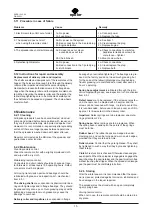
Page 18: ...g Spring base adjustment is lubricated through the lubri cation nipple with grease see inspection list mechanical item 6 3 1 Defect cams are to be replaced If the screws are rustbo und the cams can be...

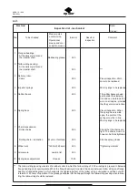
Page 19: ...st not however be firmly tightened Rolling chain lubrication Wynn s Viscotene 50 h Silicone spray grease 8 Wheel nuts 140 Nm 14 0 kpm 50 h Tightening moment 9 Air pressure see tyre list 50 h 10 Spring...

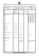
Page 20: ...13 Strickler Lubricating oil 100 h 14 Clutch lever Lubricating oil 100 h 15 Eccentric Lubricating oil 100 h 16 Stabiliser and support leg Lubricating oil 100 h 17 Nuts for drawbar 120 Nm 12 0 kpm Bef...

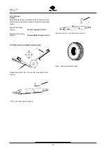
Page 21: ...se or biological lubricating grease Mineral lubricating grease Texaco Texando CX EP 2 Biological lubricating grease Texaco Biostar Grease LC EP 2 6 7 Reference to suitable spare parts Rubber base 8x21...

Page 22: ...19 epoke SKE8 12 15 20 GB 0305 1 Tested Inspection Steadying wheel Control at use Visual inspection Date Signed Result Date Signed 7 1 2...

Page 23: ...Tested Inspection Dry matter container Control at use Visual inspection Date Signed Result Date Signed Visual checks should include checks for exterior damage deformities wear and tear and corrosion I...

Page 24: ...sting height self locking nuts must only be used once i e always use new self locking nuts Nut M14 DIN 985 A2 torque is 120 Nm Do not perform subsequent changes on the drawbar e g welding repairs Chec...

Page 25: ...23 HS 82251505 10 145 CS1000 MKIII 1511 14 6 00 9 12 T 523 Steel Belt 82253612 8 1 117 45 SKE8 1001 14 6 00 9 10 T 523 82251114 8 5 123 25 SKE12 1003 14 6 00 9 12 T 523HS 82251505 10 145 14 6 00 9 12...

Page 26: ...23 epoke SKE8 12 15 20 GB 0305 1 8 1...

Page 27: ...ant requirement in order to assert oneself in international trade and frequ ently also in order to participate in open tenders The company has held the certificate since April 21 1993 and it is applic...

Page 28: ...of parts of the human body EN 418 1993 Safety of machinery Emergency stop equipment functional aspects Principles for design EN 811 1996 Safety of machinery Safety distances to prevent danger zones b...

Page 29: ...estrictions on use 4 Inspection list mechanical 16 Inspection lists and overviews 16 Instructions for Initial Operation 14 Instructions for repair and assembly 15 L Lubricating grease 7 M Machine over...

Reviews: