background image


 SMD NTC Thermistor 

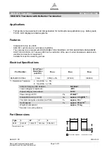
B57620C5103*062 

 SMD NTC Thermistor with Ni-Barrier Termination 


SEN NTC PD 

2009-01-12 

Please read Cautions and warnings and


Page 4 of 13 

Important notes at the end of this document

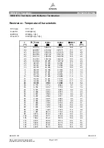
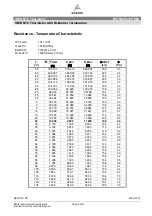
Resistance - Temperature Characteristic 


R/T-Curve 

1011 / A01 

R at 25°C 

10000 [Ohm] 

B(25/100) 

3730[K] ± 3 [%] 

Rn at 25°C 

10000 [Ohm] ± 10 [%] 


[°C] 

R_Nom 

[Ω] 

R_Min 

[Ω] 

R_Max 

[Ω] 


Δ

R/R25 

[±%] 


Δ

[±°C] 

-55 

700 137 

533 410 

866 864 

23.8 

3.5 

-50 

499 057 

385 950 

612 164 

22.7 

3.4 

-45 

360 153 

282 485 

437 820 

21.6 

3.4 

-40 

262 956 

209 015 

316 897 

20.5 

3.3 

-35 

194 112 

156 249 

231 975 

19.5 

3.3 

-30 

144 787 

117 944 

171 630 

18.5 

3.2 

-25 

109 030 

89 828 

128 233 

17.6 

3.2 

-20 

82 923 

69 057 

967 89 

16.7 

3.1 

-15 

63 591 

53 502 

73 680 

15.9 

3.0 

-10 

49 204 

41 803 

56 605 

15.0 

3.0 

-5 

38 279 

32 824 

43 733 

14.2 

2.9 

30 029 

25 980 

34 079 

13.5 

2.8 

23 773 

20 742 

26 804 

12.7 

2.8 

10 

18 959 

16 677 

21 241 

12.0 

2.7 

15 

15 207 

13 480 

16 933 

11.4 

2.6 

20 

12 280 

10 967 

13 593 

10.7 

2.5 

25 

10 000 

9 000 

11 000 

10.0 

2.4 

30 

8 178 

7 305 

9 050 

10.7 

2.7 

35 

6 734 

5 975 

7 493 

11.3 

2.9 

40 

5 575 

4 914 

6 235 

11.8 

3.2 

45 

4 636 

4 060 

5 211 

12.4 

3.4 

50 

3 874 

3 372 

4 376 

13.0 

3.6 

55 

3 237 

2 800 

3 673 

13.5 

3.9 

60 

2 720 

2 339 

3 101 

14.0 

4.2 

65 

2 304 

1 970 

2 638 

14.5 

4.4 

70 

1 960 

1 667 

2 254 

15.0 

4.7 

75 

1 674 

1 415 

1 932 

15.4 

5.0 

80 

1 434 

1 206 

1 662 

15.9 

5.2 

85 

1 235 

1 033 

1 436 

16.3 

5.5 

90 

1 067 

888,0 

1 246 

16.8 

5.8 

95 927.3 768.0 1 

087 17.2 6.1 

100 809.0 666.7  951.4 17.6 6.4 
105 706.2 579.1  833.2 18.0 6.7 
110 618.3 504.6  731.9 18.4 7.0 
115 542.8 441.0  644.6 18.8 7.3 
120 477.9 386.6  569.3 19.1 7.6 
125 422.5 340.2  504.8 19.5 7.9 


Summary of Contents for B57620C5103 062 Series

Page 1: ...text in the table and don t add any cell or line in and to it Identification Classification 1 header 1 top left header bar SMD NTC Thermistor Identification Classification 2 header 2 bottom left header bar SMD NTC Thermistor with Ni Barrier Termination Ordering code top right header bar B57620C5103 062 Series Type top right header bar Preliminary data optional if necessary Department SEN NTC PD Da...

Page 2: ...ertain hazardous substances in electrical and electronic equipment Suitable for lead free soldering process Electrical Specifications Part Number Zero Power Resistance at 25 C B25 100 B25 85 B25 50 B57620C5103 062 10 kΩ 3730 K 3 3730 K 3660 K Resistance Tolerance J for ΔR R25 5 K for ΔR R25 10 Climatic Category IEC 60068 1 55 125 21 Lower category temperature 55 C Higher category temperature 125 C...

Page 3: ...500 10 9 2 1 10 49 204 44 263 54 145 10 0 2 0 5 38 279 34 738 41 819 9 2 1 9 0 30 029 27 481 32 577 8 5 1 8 5 23 773 21 931 25 615 7 7 1 7 10 18 959 17 625 20 293 7 0 1 6 15 15 207 14 241 16 173 6 4 1 5 20 12 280 11 581 12 979 5 7 1 4 25 10 000 9 500 10 500 5 0 1 2 30 8 178 7 714 8 642 5 7 1 4 35 6 734 6 312 7 156 6 3 1 6 40 5 575 5 193 5 956 6 8 1 8 45 4 636 4 292 4 979 7 4 2 0 50 3 874 3 566 4 1...

Page 4: ...9 3 0 10 49 204 41 803 56 605 15 0 3 0 5 38 279 32 824 43 733 14 2 2 9 0 30 029 25 980 34 079 13 5 2 8 5 23 773 20 742 26 804 12 7 2 8 10 18 959 16 677 21 241 12 0 2 7 15 15 207 13 480 16 933 11 4 2 6 20 12 280 10 967 13 593 10 7 2 5 25 10 000 9 000 11 000 10 0 2 4 30 8 178 7 305 9 050 10 7 2 7 35 6 734 5 975 7 493 11 3 2 9 40 5 575 4 914 6 235 11 8 3 2 45 4 636 4 060 5 211 12 4 3 4 50 3 874 3 372...

Page 5: ...EC 60068 2 2 JIS C 0021 Storage at upper category temperature T 125 C t 1000h 3 Storage in damp heat steady state IEC 60068 2 3 JIS C 0022 Temperature of air 40 C relative humidity of air 93 Duration 21days 3 No visible damage Rapid temperature cycling IEC 60068 2 14 JIS C 0025 Lower test temperature 55 C Upper test temperature 125 C Number of cycles 10 3 Endurance at Pmax Pmax 210mW Duration 1000...

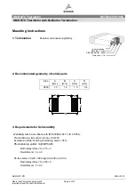
Page 6: ...r pads Size A mm B mm C mm D mm 0805 1 3 1 2 1 0 3 4 3 Requirements for Solderability Wettability test in accordance with IEC 60068 2 58 JIS C 0054 Preconditioning Immersion into flux F SW 32 Evaluation criteria Wetting of soldering areas 95 Pb containing solder Sn 60 Pb 40 Bath temperature C 215 3 Dwell time s 3 0 3 Pb free solder Sn 95 1 96 0 Ag 3 0 4 0 Cu 0 5 0 9 Bath temperature C 245 5 Dwell ...

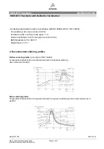
Page 7: ...ing Immersion into flux F SW 32 Evaluation criteria Leaching of side edges 1 3 Solder Sn 60 Pb 40 Sn 95 1 96 0 Ag 3 0 4 0 Cu 0 5 0 9 Bath temperature C 260 5 Dwell time s 10 1 4 Recommended soldering profiles Reflow soldering profile according to CECC 00802 Temperature characteristics at component terminals during reflow soldering two cycles are permitted Wave soldering profile Temperature charact...

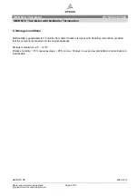
Page 8: ...nt notes at the end of this document 5 Storage conditions Solderability is guaranteed for 12 months from date of delivery for types with Ni barrier termination provided that the components are stored in the original packages Storage temperature 25 45 C Relative humidity 75 annual average 95 on max 30 days in a year dew precipitation and wetness are inadmissible ...

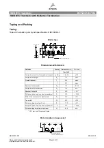
Page 9: ...ompartment height K0 1 4 max Overall thickness T2 2 5 max T 0 3 max Sprocket hole diameter D0 1 5 0 1 0 Compartment hole diameter D1 1 0 min Sprocket hole pitch P0 4 0 0 1 1 Distance centre hole to centre compartment P2 2 0 0 05 Pitch of the component compartments P1 4 0 0 1 Tape width W 8 0 0 3 Distance edge to centre of hole E 1 75 0 1 Distance centre hole to centre compartment F 3 5 0 05 Distan...

Page 10: ... min 10N Length of tape Leader section additional top cover tape length min 400 mm before component section including carrier tape with empty cavities length min 150 mm or min 20 pcs of empty cavities Trailer section length min 40 mm Empty part cavities at leader and trailer section on tape are sealed with top cover tape Cavity play Each part rests in the cavity so that the angle between the part ...

Page 11: ... Avoid contamination of thermistors surface during storage handling and processing Avoid storage of thermistor in harmful environments like corrosive gases SOx Cl etc After opening the factory seals such as polyvinyl sealed packages use the SMDs as soon as possible Solder thermistors after shipment from EPCOS within the time specified SMD with nickel barrier termination 12 months SMD with AgPd ter...

Page 12: ...ounting Ensure that adjacent materials are designed for operation at temperatures comparable to the surface temperature of the thermistor Be sure that surrounding parts and materials can withstand the temperature Avoid contamination of thermistor surface during processing Operation Use thermistors only within the specified operating temperature range Environmental conditions must not harm the ther...

Page 13: ...ird parties in the event of malfunction or failure of an electronic component 3 The warnings cautions and product specific notes must be observed 4 In order to satisfy certain technical requirements some of the products described in this publication may contain substances subject to restrictions in certain jurisdictions e g because they are classed as hazardous Useful information on this will be f...

Reviews: