EPAK DS13 PRO Installation And User Manual Download Page 23

Gateway

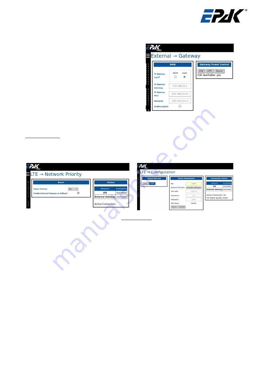
The   user   can   optionally   add   a   external   gateway   to
route a internet connection via the ACU. You can add
the IP address type (DHCP / Static).  Select the DHCP
option   if   your   default   gateway   has   DHCP   server
enabled.   Otherwise   enter   the   gateways   IP   address,
ACU IP address (should be in range of the gateway),
the Netmask and VLAN id if valid. 

If the gateway is powered by the ACU Power outlet,
then the user can power off / on or reset it. You can
also see if the gateway is reachable or not.

5.3.2

Configuration -> LTE

The   user   can   configure   network   priority   settings   and   LTE   connection   settings   in   this   section.   In   the

Network→Priority

  section select the Primary network – LTE or External Gateway.  When one is selected as

primary, then by default the other will be the fallback network. The user can choose to enable / disable the
fallback. Click on “Apply” at the top to save your changes. As a priority, the ACU will try to connect to the
primary selected network. If no internet connection is detected on the primary, and if the fallback is enabled,
then the ACU will connect to the fallback network.

The user can configure the LTE settings in the 

Network→ LTE

 section. The ACU has 2 slots for data SIMs

from multiple providers. Select the one which should be activated. In the Dialer Information box, enter your
SIM PIN if it needs to unlocked. Select the  

Network Provide

r settings – auto / manual. Some SIMs require

different APN, Username and password settings. Please check if the current settings match yours. To make
any   changes   to   the   dialer   information,   please   choose   “

manual

”   for   the   Network   Provider   and  

Save

  the

changes. Once the Dialer Information is complete, the LTE will be connected automatically.

5.3.3

Configuration -> Antenna

In   this   section,   the   user   can   select   the   antenna’s   control   on   this   page.   If   the   antenna   is   required   to
automatically track the satellite, then switch to “

Change Control: auto

”.  If the user requires the antenna to

be pointed manually (with automatic tracking off) then select “

Change Control: manual

”. Then the user can

control   the   antenna   ‘s   elevation,   azimuth   and   skew   from   the   widget  

“Manual   Control”.  

The   minimum

possible movement in any direction is 0.01°. The antenna’s position can be monitored from the “

Antenna

Parameters

” widget. 

To select a new beam, click on one of the beams under “

Change Beam

” widget on this page and the antenna

will automatically repoint to this new beam.

The user can adjust the tilt for the satellite in the “

Adjust Tilt

” widget. This feature is only used for testing

purposes and it is not required to do this for every satellite.

The “

Tracking performance”

  is to evaluate the antennas tracking features. The results of the evaluation

could be seen at the end with the results shown as “

pass

” or “

fail

”. 

 Doc ID 0354  15.12.20

Page 23/33

Summary of Contents for DS13 PRO

Page 1: ...Installation and User Manual Maritime TVRO systems DSi6Ku Pro DS6 PRO DS9 PRO DS13 PRO Doc ID 0354 15 12 20 Page 1 33...

Page 2: ...ry note sent to you with the system Disclaimer Any responsibility or liability for loss or damage in connection with the use of this product and the accompanying documentation is disclaimed by EPAK Th...

Page 3: ...he Antenna 11 4 6 Removing Transport Lock of the Antenna 11 4 7 Installing the Indoor Unit 12 4 8 Power supply for TVRO system 13 4 9 Antenna Grounding 14 4 10 System Cable Connections 15 4 11 Wiring...

Page 4: ...or configuring the antenna checking the antenna s current status and configuring your network To guarantee the highest performance and reliability EPAK designs and engineers all of its antennas major...

Page 5: ...d potential differences between the ship s ground potential and the equipment s The antenna s ground connection shall be connected directly to the ship s ground to avoid undesired current flow For det...

Page 6: ...cable and Ethernet cable Functionality Configuring satellite beams Monitoring live status of the antenna Providing Internet access voip services to the vessel Mounting screws DS6 DS9 4 mounting screws...

Page 7: ...atellite The antenna needs a free line of sight to the satellite for uninterrupted operation Any obstacles can reduce service availability and tracking performance Please note that the free line of si...

Page 8: ...and Radar with 20 vertical separation 0 20 kW 1 0 m 2 0 m 20 50 kW 2 0 m 4 0 m 50 kW 3 5 m 7 0 m The presence of one or more S or X band radars within a radius up to 100m may cause a minor degradatio...

Page 9: ...Use shrink tubing with heat activated adhesive to seal connectors Avoid sharp bends and kinks on cables To connect antenna and ACU use cables in one piece do not extend cables do not split cables Use...

Page 10: ...or full view or refer to page 31 Click for full view or refer to page 32 Doc ID 0354 15 12 20 Page 10 33 Figure 4 3 Dimensions 60 cm antenna dome front and bottom Figure 4 4 Dimensions 90 cm antenna d...

Page 11: ...to be mounted from below and through the base plate of the antenna Connect the 5 coaxial cables at the base of the antenna Close all drilled holes with waterproof sealing material to avoid any water p...

Page 12: ...th movement by turning the handle left as shown below 4 7 Installing the Indoor Unit Before installing the IDU find a suitable location for the equipment within cable lengths Ensure that the display o...

Page 13: ...s provided by EPAK or a compatible UPS on line double conversion type has to be installed by the ship owner for powering the IDU 4 8 Power supply for TVRO system The ACU requires 90 264V AC 47 63 Hz 1...

Page 14: ...fore at a very unique potential In this case this potential must not be connected within the antenna system Case 1 same potential Case 2 different potential An electrical connection should be establis...

Page 15: ...onnect the ACU and ODU as follows The Antenna Receive RX cable RX power must be connected to the ACU All 4 bands from the Antenna VL HL VH HH must be connected to the input of multiswitch The TV recei...

Page 16: ...are then able to switch between these bands and surf the TV channels The user can also connect the ship s compass to the NMEA interface of the ACU for accurate heading information This heading informa...

Page 17: ...nnect several EPAK devices together e g DivKit second ACU heating controller Use only if you are instructed to do so by a technician C Serial Connector RS232 RJ45 Connect this port to a RS232 device w...

Page 18: ...to replace a broken fuse 1 Those connectors carry the supply voltage for the antenna Do not connect or disconnect while the ACU is turned on Access to the Webinterface Connect a computer to this port...

Page 19: ...EPAK IT service In case your system has not been configured yet use the following credentials Username admin Password last 5 digits of ACU serial number Navigation Menu Upon successful login the user...

Page 20: ...ure of 12V converter T12 Temp speed in rpm of board fan fan2 speed the Central Processing Unit temperature in centigrade CPU Temp 12V converter current in Ampere I12 current air temperature inside ACU...

Page 21: ...traffic on the dynamic graphs on the right hand side of the screen 5 2 3 Status System This page is useful to monitor functionality of the system It shows the graphs of CPU load the memory statistics...

Page 22: ...nfigure the IP addresses of each LAN interface enable DHCP on each interface and also select 2 DNS servers for your system Firewall To view the current firewall configuration please click on Firewall...

Page 23: ...n box enter your SIM PIN if it needs to unlocked Select the Network Provider settings auto manual Some SIMs require different APN Username and password settings Please check if the current settings ma...

Page 24: ...te If the satellite is in the West orbit you must enter a negative number in the Position field eg 22West will be 22 To add new beams for a satellite click on Beam button and enter the beam ID receive...

Page 25: ...C and the Save button will create a backup on the ACU All the current backups are listed under the Restore window The user can choose to restore them by clicking on the desired backup file and then co...

Page 26: ...t to sustain an optimal performance of the antenna unit Clean the radome once a month using fresh water and a mild detergent to remove dirt and salt deposits Do not operate the antenna without the rad...

Page 27: ...EPAK systems are compatible with all universal LNB with LOF at 9 75 10 6 GHz 6 2 NMEA Connector Optionally the user can connect the vessel s gyro compass to the NMEA port at the back panel of the ACU...

Page 28: ...C 60945 IP class IP 30 Compass safe distance 0 5m according to IEC 60945 Position acquisition supplied by ODU Cables connectors ACU to Antenna 2x Double shielded coax cable ECOFLEX 10 with N plugs ACU...

Page 29: ...IDU Indoor Unit Ku Band The frequency range from 10 7 to 18GHz LNB A Low Noise Block is used for reception downlink of satellite signals It down converts a block of high range frequencies to lower ran...

Page 30: ...Drilling Pattern DSi6 Doc ID 0354 15 12 20 Page 30 33 Figure 8 1 Drilling Pattern 60cm TVRO...

Page 31: ...Drilling Pattern DS9 Doc ID 0354 15 12 20 Page 31 33 Figure 8 2 Drilling Pattern 90cm TVRO...

Page 32: ...Drilling Pattern DS13 Doc ID 0354 15 12 20 Page 32 33 Figure 8 3 Drilling Pattern 130cm TVRO...

Page 33: ...ons 130 cm antenna dome front and bottom 10 Figure 4 6 Position of transport locks 11 Figure 4 7 Transportation lock open closed 12 Figure 4 8 ACU Front view 12 Figure 4 9 ACU top view 13 Figure 4 10...

Reviews: