background image


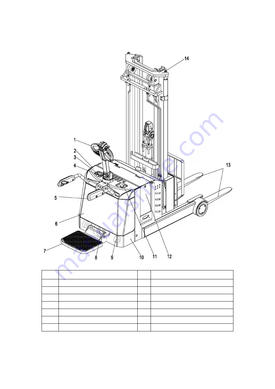
1.2 Reach Truck Assemblies 


Item  Component 

Item  Component 

Control handle 

Driving wheel 

Upper cover 

Caster wheel   

Key switch 

10  Chassis 

Battery discharge indicator   

11  Emergency stop switch 

Handrails   

12  Battery 

Lower cover 

13  Forks 

Platform   

14  Lift Mast 

Summary of Contents for CQE12R

Page 1: ...I...

Page 2: ...ordered Through our online after sales service system customers can process their warranty claims order spare parts and consult the operation manuals maintenance materials and spare parts catalogs Wit...

Page 3: ...ybe there are some differences between your product and the description in this manual And the operator manual details will be different because of customer s special requirements If you have any ques...

Page 4: ...emergency stop switch Set the key switch to the OFF position and remove the key 4 Before starting to operate Reach Truck Be in operating position Place directional control in neutral Before operating...

Page 5: ...nt that it would create a hazard 10 Reach Truck shall be kept in a clean condition to minimize fire hazards facilitate detection of loose or detective parts 11 Modifications and additions which affect...

Page 6: ...for the First Time 14 2 2 During brake in 14 3 Operation 15 3 1 Safety Regulations for the Operation of Reach Trucks 15 3 2 Operate and run the Reach Truck 16 3 2 1 Preparing 16 3 2 2 Travel Steering...

Page 7: ...Instructions 27 5 4 Decommissioning the Reach Truck 29 5 4 1 Prior to decommissioning 29 5 4 2 Restoring the Reach Truck to operation after decommissioning 30 5 5 Safety checks to be performed at reg...

Page 8: ...V I I...

Page 9: ...is considered the person who in accordance with existing contractual agreements between the owner and user of the truck is charged with operational duties The proprietor must ensure that the truck is...

Page 10: ...red drive wheel It is designed for use on level floors to lift and transport palletised goods Open bottom pallets or roll cages can be lifted The capacity can be obtained from the data plate The capac...

Page 11: ...omponent Item Component 1 Control handle 8 Driving wheel 2 Upper cover 9 Caster wheel 3 Key switch 10 Chassis 4 Battery discharge indicator 11 Emergency stop switch 5 Handrails 12 Battery 6 Lower cove...

Page 12: ...backward or forward 15 Reach backward forward button Reach the mast backward or forward 16 Lower Lift button Lowers or Raises load forks 17 Right Left button Reach the fork right or left Optional 18 T...

Page 13: ...0 one lit red segment and one flashing red segment Battery discharged at 80 two flashing red segments Lifting is inhibited The battery must be charged Operating hours display 2 Display range between 0...

Page 14: ...olding operator pedal can fold self motion 1 2 5 Side arm Travel speed Max will change when the state of side arm is changed Travel speed Max is much higher when the side arm is unfolded The side arm...

Page 15: ...ear fork retracted 1286 539 1425 610 kg Laden Front Rear fork advanced 454 2510 391 3093 kg Laden Front Rear fork retracted 1110 1875 1244 2237 kg Drive motor rating S2 60 min 1 5 1 5 kW Lift motor ra...

Page 16: ...766 mm Wa Outer turning radius 1597 1697 mm l7 Length across wheel arms exclusive fork 1700 1822 mm Tyre type polyurethane polyuret hane polyurethane polyuret hane Tyre size driving wheels 230 75 260...

Page 17: ...4000 5000 2715 0 4300 5300 Triplex Mast 1735 740 3500 4500 1900 905 4000 5000 2065 1070 4500 5500 2165 1170 4800 5800 2230 1235 5000 6000 2395 1400 5500 6500 For Shifter Side Duplex Mast 1815 0 2500 3...

Page 18: ...Side Duplex Mast Triplex Mast Duplex Mast Triplex Mast Duplex Mast Triplex Mast Duplex Mast Triplex Mast Overall length minimum l1 2312 2354 2347 2389 2332 2379 2367 2413 Length to face of forks l2 12...

Page 19: ...11...

Page 20: ...tion 1 Direction decal on control handle 6 AC Power Decal 2 No passengers Decal 7 Emergency stop switch Decal 3 Reach Truck data plate 8 Never put your hands in inner warning 4 Key Switch Decal 9 Stra...

Page 21: ...5 Date of build 13 Load center 6 Truck weight with battery 14 Load capacity 7 Truck weight without battery 15 Max battery weight 8 Voltage 16 Min battery weight For queries regarding the Reach Truck o...

Page 22: ...s will flatten The flattening will disappear after a short period of operation 2 2During brake in We recommended operating the machine under light load conditions for the first stage of operation to g...

Page 23: ...rsonnel Damage and Faults The supervisor must be immediately informed of any damage or faults to the Reach Truck Reach Trucks not safe for operation e g wheel or brake problems must not be used until...

Page 24: ...ke sure the battery is connected Insert the key in the key switch 14 and turn it to the right as far as it will go Test the warning signal switch 13 Visually inspect the entire reach truck in particul...

Page 25: ...ndle 1 to the left or right 3 Braking The brake pattern of the Reach Truck depends largely on the ground conditions The driver must take this into account when operating the Reach Truck The driver mus...

Page 26: ...e load from tipping or falling down Do not transport witch bad handbarrow as Reach Truck and stock Never stand underneath a raised load handler Do not stand on the load handler Do not lift other peopl...

Page 27: ...t Left button 17 until the location you need Sideshift right Press Right Left button 17 until the location you need 3 2 4 Parking the Reach Truck securely When you leave the Reach Truck it must be sec...

Page 28: ...ck is parked for charging there shall be no inflammable material or operating fluids capable of creating sparks within 2 meters around the Reach Truck The area must be well ventilated Fire protection...

Page 29: ...connector 2 Pull out the battery plate 3 Pull out the battery 4 When replacing a battery always use the same battery type Extra weights must not be removed and must remain in the same position NOTE Th...

Page 30: ...ection regulations or disposal laws The manufacturer s disposal instructions must be followed Batteries contain an acid solution which is poisonous and corrosive Therefore always wear protective cloth...

Page 31: ...viced and maintained by the manufacturer s trained personnel The manufacturer s service department has field technicians specially trained for these tasks We therefore recommend a maintenance contract...

Page 32: ...els and tyres ensure that the Reach Truck does not slew e g when replacing wheels always left and right simultaneously 5 3 Servicing and inspection Thorough and expert servicing is one of the most imp...

Page 33: ...eck travel mechanism adjust and lubricate if necessary Check control handle recuperating function Check driving wheel and loading wheel for wear and damage Check wheel bearings and attachments Reach T...

Page 34: ...26 5 3 2 Lubrication Schedule...

Page 35: ...e mixture must be disposed of in accordance with regulations Code Description Used for A HM46 Hydraulic system B Polylub GA352P Lubrication grease C GL5 80W 90 gear case 5 3 3 Maintenance Instructions...

Page 36: ...ation Schedule If necessary add transmission oil of the correct grade See 5 3 2 Lubrication Schedule Installation is the reverse order Checking electrical fuses Prepare the Reach Truck for maintenance...

Page 37: ...ent 5 4 1Prior to decommissioning Thoroughly clean the Reach Truck Check the brakes Check the hydraulic oil level and replenish as necessary See 5 3 3 Maintenance Instructions Apply a thin layer of oi...

Page 38: ...ual event by a qualified inspector The inspector shall assess the condition of the Reach Truck from purely a safety viewpoint without regard to operational or economic circumstances The inspector shal...

Page 39: ...ow Faulty fuse Reach Truck in charge mode Set key switch to I Check battery charge charge battery if Necessary Test fuses Interrupt charging Load can not be lifted Hydraulic oil level too low Excessiv...

Reviews: