13
EN
Connecting the sensor cable
You should not draw sensor and power supply
cables together or lead them through the same
duct. This can lead to interferences in the elec-
tronics, such as "fluttering" in the relays. If it is
necessary to lay the cables down together, or if
the sensor line is longer than 3m, use a shielded
sensor cable (2 x 0.5 mm²).
Connect the shielding to ground in the control
unit.
Please observe that the following dimensions
relate to the values stipulated during the unit
inspection acc. EN 60335-2-53. The room tem-
perature sensor must always be mounted on
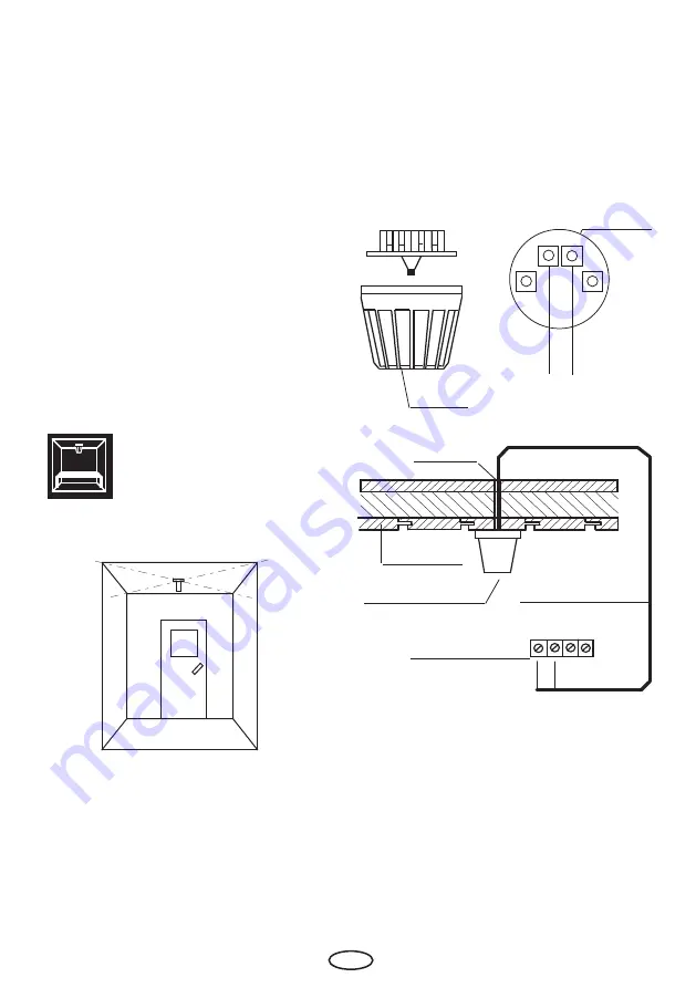
the ceiling in the centre of the cabin. The fol-
lowing Figs. give you an overview of the instal-
lation point for the sensor.
1. The heater sensor is mounted in the centre of
the cabin ceiling.
Housing
S e n s o r c i r c u i t
board
Sensor
S1 S2
Hole
Cabin ceiling
Centre sensor housing on
middle section
Sensor cable
Terminals in control
unit
2. Drill a hole to lead the cable through, prefer-
ably through the middle of one of the wood-
en boards.
3. Draw the sensor cable through the drilled
hole and connect it to the sensor board ac-
cording to the Fig. below.
Installation of the room sen-
sor


