background image

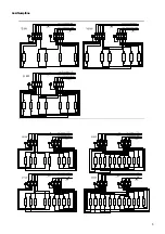
Terminal connection diagrams

11

to 9 kW power control unit

to 6 kW control unit

1

2

3

4

to 9 kW power control unit

to 9 kW control unit

to 9 kW power control unit

to 9 kW control unit

5 x 1,5

2

5 x 1,5

2

5 x 1,5

2

5 x 1,5

2

5 x 2,5

5 x 1,5

2

3,0 kW

3,0 kW

3,0 kW

3,0 kW

3,0 kW

3,0 kW

3,0 kW

15 kW

18 kW

21 kW

2

N W V U

PE

PE

4 3 2 1

U

V

W

N

W

PE

4 3

N

2 1

U

V

PE

4

N

3 2 1

V

W

U

3,0 kW

3,0 kW

3,0 kW

3,0 kW

3,0 kW

3,0 kW

3,0 kW

3,0 kW

3,0 kW

3,0 kW

3,0 kW

N

PE

4 3 2 1

V

W

U

PE

U

4 3 2 1

W

N

V

to 18 kW power control unit

to 18 kW control unit

5 x 1,5

2

5 x 4

2

36 kW

3,0 kW

N

PE

4 3 2 1

V

W

U

PE

U

4 3 2 1

W

N

V

5

5

3,0 kW

3,0 kW

3,0 kW

3,0 kW

3,0 kW

3,0 kW

3,0 kW

3,0 kW

3,0 kW

3,0 kW

3,0 kW

3,0 kW

3,0 kW

3,0 kW

PE

4

5

2

3

1

3,0 kW

3,0 kW

3,0 kW

3,0 kW

3

PE

5 4

2 1

3,0 kW

3,0 kW

to  9 kW control unit

to 18 kW power control unit

27 kW

N

V

W

U

5 x 1,5

2

N W V U

5 x 4

2

2

3,0 kW

3,0 kW

3,0 kW

PE

4

5

3

3,0 kW

3,0 kW

3,0 kW

1

PE

5 4 3 2

3,0 kW

3,0 kW

1

24 kW

N W

V

to  9 kW control unit

to 15 kW power control unit 

5 x 1,5

V U

2

N W

5 x 4

U

2

3,0 kW

3,0 kW

3,0 kW

3,0 kW

3,0 kW

5

PE

3

4

1

2

3,0 kW

3,0 kW

3,0 kW

3,0 kW

PE

2

4

5

3

1

3,0 kW

to 15 kW power control unit

to 15 kW control unit

30 kW

W

N

V U

5 x 4

2

N W V U

5 x 4

2

Summary of Contents for 34.G Series

Page 1: ...10 12 15 18 21 24 27 30 36 4 4 6 6 8 7 10 9 14 14 18 18 25 24 30 24 34 35 40 40 50 50 65 65 75 Heiz leistung in kW Anschluss an 400V 3N AC Absicherung A 3 x 25 3 x 35 3 x 50 3 x 63 Mindestquerschnitt...

Page 2: ...der Bank oder unter ei ner Dachschr ge bestimmt l Das Saunaheizger t nicht bei geschlossener Luftein tritts ffnung in Betrieb nehmen l Die Kabinenbeleuchtung mit der dazugeh renden In stallation muss...

Page 3: ...s Saunaheizger t und das Steuerger t aufeinander abgestimmt sind Beachten Sie die Angaben und Informationen Ihres Sau na Lieferanten Die Saunaheizger te erw rmen Ihre Saunakabine durch aufgeheizte Kon...

Page 4: ...ger t LSG 18 90 7372 00 Sicherheitssch tz N N Sicherheitssch tz 5 x 1 5 2 x 1 5 5 x 2 5 5 x 6 Abzweigkasten Netzschalter 3 x 16 A 12 16 kW 4 18 21 kW 6 24 27 kW 10 L1 L2 L3 N L3 L2 L1 Sauna Steuerger...

Page 5: ...Anschlusspl ne 5...

Page 6: ...ca alle 6 Wochen damit sich die Heizst be nicht mit Feuchte anreichern k nnen F r den ordnungsgem en Anschluss der Heizger te ist der Elektroinstallateur verantwortlich und somit ist eine Haftung dur...

Page 7: ...5 x 4 5 x 6 5 x 10 min 5 x 10 12 15 18 21 24 27 30 36 4 4 6 6 8 7 10 9 14 14 18 18 25 24 30 24 34 35 40 40 50 50 65 65 75 Heat output in kW Connection to 400 V 3N AC FuseA 3 x 25 3 x 35 3 x 50 3 x 63...

Page 8: ...ct with the unit can cause burns l The sauna heating unit is not designed for installation use in a niche beneath the reclining bench or beneath an inclined ceiling l The sauna heating unit must not b...

Page 9: ...haust system the sauna heater and the control unit are designed and set to work efficiently in combination Please observe the instructions and information provided by your sauna supplier Saunaheatingu...

Page 10: ...ol unit LSG 18 90 7372 00 safety contactor N N safety contactor 5 x 1 5 2 x 1 5 5 x 2 5 5 x 6 junction box Mains switch 3 x 16 A 12 16 kW 4 18 21 kW 6 24 27 kW 10 L1 L2 L3 N L3 L2 L1 Sauna Steuerger t...

Page 11: ...ontrol unit to 18 kW control unit 5 x 1 52 5 x 42 36 kW 3 0 kW N PE 4 3 2 1 V W U PE U 4 3 2 1 W N V 5 5 3 0 kW 3 0 kW 3 0 kW 3 0 kW 3 0 kW 3 0 kW 3 0 kW 3 0 kW 3 0 kW 3 0 kW 3 0 kW 3 0 kW 3 0 kW 3 0...

Page 12: ...is not going to be used for a long period we recommend that it is heated up about every 6 weeks so that the heating rods do not attract moisture The electrician is responsible for connecting the heat...

Page 13: ...13...

Page 14: ...14...

Reviews: