
Copyright EnvironmentalLights.com
All Rights Reserved 10/1/18
5
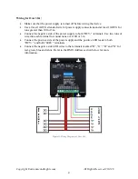
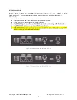
DMX Connection:
Both the DMX-4-5000-3-10A and DMX-4-5000-5-10A each have four ports available for DMX
input and output. Pin out diagrams for both are shown below in Figure III and Figure IV
respectively.
•
Each decoder can have only one DMX input signal at a time.
•
Either RJ45 port can be used as an input or output.
•
The DMX IN port should be used for DMX input when connecting with DMX cables.
•
The DMX OUT port can be used as a DMX pass-through.
•
If the DMX OUT port is not being used, move slider #10 on the DIP switch to the “ON”
position to engage the internal termination.
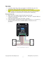
Figure III: Connector Pinout for DMX-4-5000-3-10A
Figure IV: Connector Pinout for DMX-4-5000-5-10A