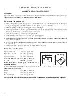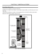
The minimum clearance to combustibles is 6” (150 mm) when using single wall venting and 1” (25 mm)
when using “B-vent” venting.
We strongly recommend installing an approved chimney liner in an existing brick chimney. This will
maximize the potential draft of the chimney and lessen the effects of slow chimney start-up.
VENTING OF A FIREPLACE FITTED WITH THE DRAFTHOOD ADAPTOR:
Note:
Please refer to the chimney manufacturer’s installation instructions prior to commencing the
installation.
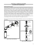
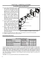
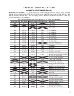
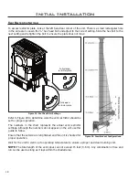
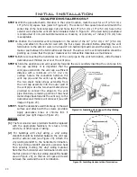
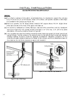
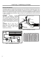
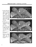
Figure 40: Unit top venting styles.
�� ������
����
�� ������
��������
����������
�����
����� ���� �����
�� ��� ��� ��� ��
��������
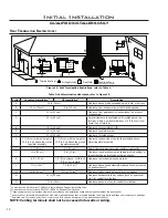
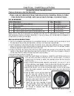
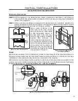
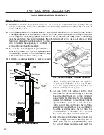
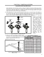
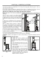
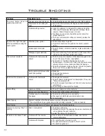
Figure 42: Draft test place.
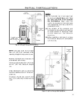
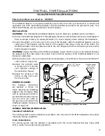
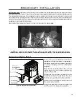
Figure 41: Unit rear venting
style.
mm) must be maintained between the vent connector and any combustibles.
CAUTION:
A minimum vent height of 12’ (3.6 m) from the floor is required to effectively vent this
fireplace.
This unit may be vented to an existing masonry
chimney, or where no masonry chimney is available,
an approved “B-vent” chimney, or any other approved
constructed chimney/vent system (see Figure 40 &
41).
In either case, the fireplace may be connected to
the chimney/vent using a 4” (10 cm) single wall vent
connector.
When an existing masonry chimney is utilized for
the venting, we recommend the vent connector be
connected to an approved 4” (10 cm) diameter flue
liner running the full height of the chimney. In many
jurisdictions this flue liner may be mandatory.
If 4” (10 cm) single wall vent is used, a minimum of
6” (15 cm) must be maintained between the vent
connector and any combustibles.
If 4” (10 cm) “B-vent” is used a minimum of 1” (25
Initial Installation
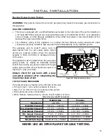
SPILLAGE TEST:
A spillage test must be performed prior
to leaving the installed fireplace with the
customer. Perform this test in the following
manner:
1. Close all windows and doors in the room.
2. Start all exhaust fans in the house and the
furnace blower.
3. Light the fireplace and set to maximum
flame adjustment.
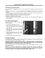
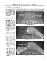
4. After a minimum of 10 minutes operation,
test the chimney draft with a smoke match
at the top row of the pattern to confirm
that there is adequate draft or ‘pull’ at the
openings around the body of the Drafthood
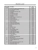
Adaptor, as shown in Figure 43.
26

