background image

EntraGuard

®

 Platinum Telephone Entry Controller

Installation Guide

Page 3 of 10

P/N: 01553-001 Rev. D

1.3

New Style Platinum Controller

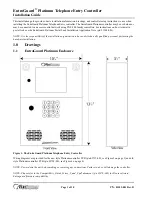
Figure 3: New Style Entraguard Platinum Controller – p/n 05735-001

Alarm

Relay

Lock

Relay

GP

Output

Relay 2

GP

Output

Relay 1

6

5

4

3

2

1

6

5

4

3

2

1

6

5

4

3

2

1

3

2

1

6

5

4

3

2

1

1

2

3

2

1

485

U18

U2

Battery

D4

D5

D6

D20

D18

D30

D29

D25

D32

SW1

R75

J3

J1

J6

J8

Internal
Modem

J11

J16 - Postal Lock Connection

JP1

JP2

J19

J20

LED Backlight

Connection

J13

U5

J9

TB15

TB1

TB2

TB3

TB4

TB10

TB12

1) Door Switch - NC
2) Ground
3) Request to Exit - NO
4) - not available-
5) Ground
6) Global Unlock - NO
    or Auxiliary RTE - NO

TB4 - Inputs

1) Lock - NO
2) Lock - Common
3) Lock - NC
4) Alarm - NO
5) Alarm - Common
6) Alarm - NC

TB3 - Lock &

Alarm Relays

1) GP1 - NO
2) GP1 - Common
3) GP1 - NC
4) GP2 - NO
5) GP2 - Common
6) GP2 - NC

TB10- General

Purpose Outputs

1) Tx/Rx -
2) Tx/Rx +
3) Shield

TB1 - RS-485

Network

1) +12 VDC
2) Negative (Ground)
3) Earth Ground

TB2 - 12 VDC Power

TB15 - Wired Telephone Connection

1) TIP

2) Ring

J9 - Standard Phone Jack Connection

U39

J10

LAN

Communication

Jumpers

Modem Module

RxD

DTR

TxD

TB12 - RS-232 Serial Port Connection

Pin 3 (RxD) to Pin 1 (TxD)
Pin 2 (TxD) to Pin 2 (RxD)

Pin 7 (RTS) to Pin 4 (RTS)

Pin 4 (DTR) to Pin 5 (DTR)

Pin 5 (Gnd) to Pin 6 (Gnd)

Modem Side DB-9M

(back side of connector)

6

5

4

3

2

1

TB12 - Modem Connection

2

3

4

5

7

1

2

3

4

5

6

Pin 2 (RxD) to Pin 1 (TxD)

Pin 3 (TxD) to Pin 2 (RxD)

Pin 5 (Gnd) to Pin 6 (Gnd)

2

3

5

PC Side DB-9F
(back side of connector)

TB12 - Direct to PC Connection

Keri p/n: KDP-552

Keri p/n: KDP-929M

J7
LAN-520
Connection

Summary of Contents for Platinum

Page 1: ... Application Note p n 01964 001 NOTE It is the responsibility of the installation organization to have only technically qualified personnel performing the hardware installation 1 0 Drawings 1 1 EntraGuard Platinum Enclosure Figure 1 The EntraGuard Platinum Telephone Entry Controller Wiring diagrams are provided for the new style Platinum controller PCB p n 05735 001 see Figure 3 on page 3 and old ...

Page 2: ...ation Guide Page 2 of 10 P N 01553 001 Rev D 1 2 Enclosure Mounting Diagram Figure 2 Entraguard Platinum Mounting Diagram 0 00 0 552 1 553 9 686 10 235 0 00 1 001 6 892 10 888 11 223 12 48 13 808 all units in inches 0 256 dia 1 374 dia 0 386 dia 0 258 dia ...

Page 3: ...Lock Common 3 Lock NC 4 Alarm NO 5 Alarm Common 6 Alarm NC TB3 Lock Alarm Relays 1 GP1 NO 2 GP1 Common 3 GP1 NC 4 GP2 NO 5 GP2 Common 6 GP2 NC TB10 General Purpose Outputs 1 Tx Rx 2 Tx Rx 3 Shield TB1 RS 485 Network 1 12 VDC 2 Negative Ground 3 Earth Ground TB2 12 VDC Power TB15 Wired Telephone Connection 1 TIP 2 Ring J9 Standard Phone Jack Connection U39 J10 LAN Communication Jumpers Modem Module...

Page 4: ...EntraGuard Platinum Telephone Entry Controller Installation Guide Page 4 of 10 P N 01553 001 Rev D 1 4 Old Style Platinum Controller Figure 4 Old Style Entraguard Platinum Controller p n 05728 001 ...

Page 5: ...Guide Page 5 of 10 P N 01553 001 Rev D 1 5 Board Placement for a PXL 500 Controller Figure 5 Platinum Board Placement with an Optional PXL 500 Controller NOTE For information on the optional PXL 500 PXL 510 board see the PXL 500 Installation Guide P N 01530 001 ...

Page 6: ...tion between controller and host PC serial RS 232 or LAN 3 1 Serial RS 232 An RS 232 serial port connection is made by either a direct serial connection 50 feet maximum through an internal PC modem or external modem USB to serial converter uses the Direct to PC serial connection NOTE If your PC has an internal modem that modem may be prevented by the PC from properly operating with an Entraguard c...

Page 7: ...et Menu the unit must be powered up again 4 1 Set Unit Address The controller s address may only be set through the Reset Menu To set the desired operating address for the controller press 1 on the keypad The Set New Unit Address screen appears on the LCD see Figure 7 Figure 7 Set Unit Address The address range is from 1 to 128 The Master Controller must be set to address 1 Other slave EntraGuard ...

Page 8: ...ry needs to be cleared of any spurious information that may be in the RAM If you changed the controller address the memory is automatically cleared However if you did not change the address you will need to clear the controller s RAM separately From the Reset Menu see Figure 6 on page 7 press 2 to Clear Memory The Clear Memory screen will appear on the LCD see Figure 9 Figure 9 Clear Memory From t...

Page 9: ... The default is set for the large size However if the small size font would be preferred as the default it may be changed through the reset menu From the Reset Menu see Figure 6 on page 7 press 5 for LCD Setup The LCD Setup menu will appear on the LCD see Figure 11 Figure 11 Setup LCD Menu 1 Select 5 on the keypad to change the default font size The Set Font Default Menu appears see Figure 12 Figu...

Page 10: ... Contact Keri Systems end of document Keri USA Keri UK Ireland Europe 2305 Bering Drive San Jose CA 95131 Unit 17 Park Farm Industrial Estate Ermine Street Buntingford Herts SG9 9AZ UK Telephone 800 260 5265 408 435 8400 Telephone 44 0 1763 273 243 Fax 408 577 1792 Fax 44 0 1763 274 106 Web www kerisys com Web www kerisystems co uk E mail sales kerisys com techsupport kerisys com E mail sales keri...

Reviews: