background image

vii

3.

APPLICABLE


LAW.

This


Agreement


shall


be


interpreted


and


governed


under


the


laws


and


in


the


state


and


federal


courts


of


the


Commonwealth


of


Massachusetts


without


regard


to


its


conflicts


of


laws


provisions.


You


accept


the


personal


jurisdiction


and


venue


of


the


Commonwealth


of


Massachusetts


courts.


None


of


the


1980


United


Nations


Convention


on


Contracts


for


the


International


Sale


of


Goods,


the


United


Nations


Convention


on


the


Limitation


Period


in


the


International


Sale


of


Goods,


and


the


Uniform


Computer


Information


Transactions


Act


shall


apply


to


this


Agreement.


4.

EXPORT


RESTRICTIONS.

You


understand


that


Enterasys


and


its


Affiliates


are


subject


to


regulation


by


agencies


of


the


U.S.


Government,


including


the


U.S.


Department


of


Commerce,


which


prohibit


export


or


diversion


of


certain


technical


products


to


certain


countries,


unless


a


license


to


export


the


Program


is


obtained


from


the


U.S.


Government


or


an


exception


from


obtaining


such


license


may


be


relied


upon


by


the


exporting


party.

If


the


Program


is


exported


from


the


United


States


pursuant


to


the


License


Exception


CIV


under


the


U.S.


Export


Administration


Regulations,


You


agree


that


You


are


a


civil


end


user


of


the


Program


and


agree


that


You


will


use


the


Program


for


civil


end


uses


only


and


not


for


military


purposes.


If


the


Program


is


exported


from


the


United


States


pursuant


to


the


License


Exception


TSR


under


the


U.S.


Export


Administration


Regulations,


in


addition


to


the


restriction


on


transfer


set


forth


in


Sections


1


or


2


of


this


Agreement,


You


agree


not


to


(i)


reexport


or


release


the


Program,


the


source


code


for


the


Program


or


technology


to


a


national


of


a


country


in


Country


Groups


D:1


or


E:2


(Albania,


Armenia,


Azerbaijan,


Belarus,


Bulgaria,


Cambodia,


Cuba,


Estonia,


Georgia,


Iraq,


Kazakhstan,


Kyrgyzstan,


Laos,


Latvia,


Libya,


Lithuania,


Moldova,


North


Korea,


the


People’s


Republic


of


China,


Romania,


Russia,


Rwanda,


Tajikistan,


Turkmenistan,


Ukraine,


Uzbekistan,


Vietnam,


or


such


other


countries


as


may


be


designated


by


the


United


States


Government),


(ii)


export


to


Country


Groups


D:1


or


E:2


(as


defined


herein)


the


direct


product


of


the


Program


or


the


technology,


if


such


foreign


produced


direct


product


is


subject


to


national


security


controls


as


identified


on


the


U.S.


Commerce


Control


List,


or


(iii)


if


the


direct


product


of


the


technology


is


a


complete


plant


or


any


major


component


of


a


plant,


export


to


Country


Groups


D:1


or


E:2


the


direct


product


of


the


plant


or


a


major


component


thereof,


if


such


foreign


produced


direct


product


is


subject


to


national


security


controls


as


identified


on


the


U.S.


Commerce


Control


List


or


is


subject


to


State


Department


controls


under


the


U.S.


Munitions


List.

5.

UNITED


STATES


GOVERNMENT


RESTRICTED


RIGHTS.

The


enclosed


Program


(i)


was


developed


solely


at


private


expense;


(ii)


contains


“restricted


computer


software”


submitted


with


restricted


rights


in


accordance


with


section


52.227

19


(a)


through


(d)


of


the


Commercial


Computer


Software

Restricted


Rights


Clause


and


its


successors,


and


(iii)


in


all


respects


is


proprietary


data


belonging


to


Enterasys


and/or


its


suppliers.


For


Department


of


Defense


units,


the


Program


is


considered


commercial


computer


software


in


accordance


with


DFARS


section


227.7202

3


and


its


successors,


and


use,


duplication,


or


disclosure


by


the


Government


is


subject


to


restrictions


set


forth


herein.


6.

DISCLAIMER


OF


WARRANTY.

EXCEPT


FOR


THOSE


WARRANTIES


EXPRESSLY


PROVIDED


TO


YOU


IN


WRITING


BY


ENTERASYS,


ENTERASYS


DISCLAIMS


ALL


WARRANTIES,


EITHER


EXPRESS


OR


IMPLIED,


INCLUDING


BUT


NOT


LIMITED


TO


IMPLIED


WARRANTIES


OF


MERCHANTABILITY,


SATISFACTORY


QUALITY,


FITNESS


FOR


A


PARTICULAR


PURPOSE,


TITLE


AND


NON

‐ 

INFRINGEMENT


WITH


RESPECT


TO


THE


PROGRAM.


IF


IMPLIED


WARRANTIES


MAY


NOT


BE


DISCLAIMED


BY


APPLICABLE


LAW,


THEN


ANY


IMPLIED


WARRANTIES


ARE


LIMITED


IN


DURATION


TO


THIRTY


(30)


DAYS


AFTER


DELIVERY


OF


THE


PROGRAM


TO


YOU.


7.

LIMITATION


OF


LIABILITY.

IN


NO


EVENT


SHALL


ENTERASYS


OR


ITS


SUPPLIERS


BE


LIABLE


FOR


ANY


DAMAGES


WHATSOEVER


(INCLUDING,


WITHOUT


LIMITATION,


DAMAGES


FOR


LOSS


OF


BUSINESS,


PROFITS,


BUSINESS


INTERRUPTION,


LOSS


OF


BUSINESS


INFORMATION,


SPECIAL,


INCIDENTAL,


CONSEQUENTIAL,


OR


RELIANCE


DAMAGES,


OR


OTHER


LOSS)


ARISING


OUT


OF


THE


USE


OR


INABILITY


TO


USE


THE


PROGRAM,


EVEN


IF


ENTERASYS


HAS


BEEN


ADVISED


OF


THE


POSSIBILITY


OF


SUCH


DAMAGES.


THIS


FOREGOING


LIMITATION


SHALL


APPLY


REGARDLESS


OF


THE


CAUSE


OF


ACTION


UNDER


WHICH


DAMAGES


ARE


SOUGHT.

THE


CUMULATIVE


LIABILITY


OF


ENTERASYS


TO


YOU


FOR


ALL


CLAIMS


RELATING


TO


THE


PROGRAM,


IN


CONTRACT,


TORT


OR


OTHERWISE,


SHALL


NOT


EXCEED


THE


TOTAL


AMOUNT


OF


FEES


PAID


TO


ENTERASYS


BY


YOU


FOR


THE


RIGHTS


GRANTED


HEREIN.


Summary of Contents for SecureStack B3G124-24P

Page 1: ...7 5x9 inch cover with bleed on 4 sides SecureStack C3 PoE Gigabit Ethernet Switches Hardware Installation Guide C3G124 24P C3G124 48P P N 9034277...

Page 2: ......

Page 3: ...Enterasys Networks Inc 50 Minuteman Road Andover MA 01810 2006 Enterasys Networks Inc All rights reserved Part Number 9034277 June 2006 ENTERASYS ENTERASYS NETWORKS ENTERASYS MATRIX LANVIEW NETSIGHT W...

Page 4: ...ss A limits for radio noise emissions from digital apparatus set out in the Radio Interference Regulations of the Canadian Department of Communications Le pr sent appareil num rique n met pas de bruit...

Page 5: ...WEEE Notice In accordance with Directive 2002 96 EC of the European Parliament on waste electrical and electronic equipment WEEE 1 The symbol above indicates that separate collection of electrical an...

Page 6: ...adjustment Class 1 Laser transceivers comply with the following safety standards 21 CFR 1040 10 and 1040 11 U S Department of Health and Human Services FDA IEC Publication 825 International Electrote...

Page 7: ...xus House Newbury Business Park London Road Newbury Berkshire RG14 2PZ England Conformance to Directive s Product Standards EC Directive 89 336 EEC EN 55022 EN 61000 3 2 EN 61000 3 3 EN 55024 EC Direc...

Page 8: ...OVISIONS THE LICENSE THE DISCLAIMER OF WARRANTY AND THE LIMITATION OF LIABILITY IF YOU DO NOT AGREE TO THE TERMS OF THIS AGREEMENT OR ARE NOT AUTHORIZED TO ENTER INTO THIS AGREEMENT ENTERASYS IS UNWIL...

Page 9: ...l security controls as identified on the U S Commerce Control List or iii if the direct product of the technology is a complete plant or any major component of a plant export to Country Groups D 1 or...

Page 10: ...edge and agree that any breach of Sections 2 4 or 9 of this Agreement by You may cause Enterasys irreparable damage for which recovery of money damages would be inadequate and that Enterasys may be en...

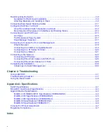
Page 11: ...guration Using WebView 1 7 Switch Configuration Using CLI Commands 1 7 Standards Compatibility 1 7 LANVIEW Diagnostic LEDs 1 8 Chapter 2 Network Requirements 10BASE TX Network 2 2 100BASE TX Network 2...

Page 12: ...3 20 Connecting to a Modem 3 21 Connecting to the Network 3 22 Connecting UTP Cables 3 22 Connecting Fiber Optic Cables to MT RJ Ports 3 26 Connecting Fiber Optic Cables to LC Ports 3 28 Completing th...

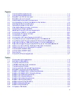
Page 13: ...ts for 10 100 1000BASE TX 3 25 3 17 Eight Wire Straight Through Cable RJ45 Pinouts for 10 100 1000BASE TX 3 25 3 18 Cable Connection to MT RJ Multimode Fiber Optic Connectors 3 27 3 19 Cable Connectio...

Page 14: ...xii...

Page 15: ...lling and setting up the stackable switches Note In this guide the following terms are used Switch refers to both C3G124 24P and C3G124 48P unless otherwise noted MGBIC Mini Gigabit Interface Card ref...

Page 16: ...p www enterasys com support manuals Unlike the SecureStack C3 Configuration Guide click on Overview Guides at the manuals web site to find the Cabling Guide For Refer to An overview of the switch feat...

Page 17: ...cal Hazard Warns against an action that could result in personal injury or death due to an electrical hazard Riesgo Electrico Advierte contra una acci n que pudiera resultar en lesi n corporal o la mu...

Page 18: ...k environment such as layout cable type other relevant environmental information Network load and frame size at the time of trouble if known The device history for example if you have returned the dev...

Page 19: ...rnal power supply failure in the switch or AC power source You can install the switch on a flat surface or into a standard 19 inch rack with user supplied mounting hardware and configure the switch fu...

Page 20: ...T ports For example if SFP port 24 establishes a link first on the C3G124 24P the 10 100 1000BASE T built in RJ45 port 24 is not available and vice versa Caution The C3G124 24P and C3G124 48P are PoE...

Page 21: ...to the C2RPS POE using a C2RPS POE cable The 10 100 1000 Mbps fixed front panel ports can operate in either half duplex or full duplex mode as determined by Auto Negotiation Note The Mini GBIC ports...

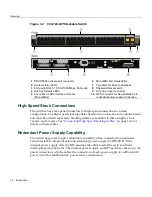
Page 22: ...nal SecureStack PoE compliant external redundant power supply C2RPS POE If the internal power supply fails the RPS assumes the entire load of the switch without interrupting network traffic The intern...

Page 23: ...ther pair provides a path for the return current While several proprietary legacy implementations of PoE have been deployed by LAN equipment vendors in 2003 the IEEE published the IEEE 802 3af 2003 sp...

Page 24: ...ctor For optical and operating range specifications refer to MGBIC LC03 Specifications 1000BASE SX on page A 5 MGBIC LC09 Provides one 1000BASE LX compliant LC fiber optic single mode port with a stan...

Page 25: ...r simple management tasks Switch Configuration Using CLI Commands The CLI commands enable you to perform more complete switch configuration management tasks For CLI command set information and how to...

Page 26: ...ANVIEW Diagnostic LEDs LANVIEW diagnostic LEDs serve as an important troubleshooting aid by providing an easy way to observe the status of individual ports and overall network operations Refer to Usin...

Page 27: ...work 2 2 1000BASE FX Network 2 2 1000BASE T Network 2 2 Note The network installation must meet the requirements described in this chapter to ensure satisfactory performance of this equipment Failure...

Page 28: ...support RJ45 copper 1000BASE T compliant connections When connecting a 1000BASE T segment to one of the RJ45 fixed ports use Category 5 UTP cabling or better The device at the other end of the twisted...

Page 29: ...is Installationen sollten nur durch ausgebildetes und qualifiziertes Personal vorgenommen werden Important Notice Read the Release Notes shipped with the switch to check for any exceptions to the supp...

Page 30: ...1 Open the box and remove the packing material protecting the switch 2 Verify that the contents of the carton contains the items listed in Table 3 1 3 Remove the tape seal on the non conductive bag to...

Page 31: ...os para ver el laser El uso de instrumentos opticos para ver el laser incrementa el riesgo de perdida de la vision Warnhinweis Benutzen sie keinesfalls optische Hilfmittel um die Funktion des Lasers z...

Page 32: ...llows 1 Hold the Mini GBIC with the top side positioned as shown and the 7 pin edge connector facing the port slot 2 Carefully align the Mini GBIC with the port slot 3 Push the Mini GBIC into the port...

Page 33: ...Use an antistatic wrist strap and observe all static precautions during this procedure Failure to do so could result in damaging the Mini GBIC or host device Always leave the Mini GBIC in the antista...

Page 34: ...optic connector insert its protective dust cover to protect the ends of the fiber optic fibers from dust and contamination Installing the Switch on a Flat Surface When installing the switch on a flat...

Page 35: ...et return the switch to its upright position 6 To install switches on a flat surface proceed to Guidelines for Flat Surface Installation on page 3 8 For a rackmount installation proceed to Rack Mounti...

Page 36: ...15 for power connection instructions Figure 3 4 Area Guidelines for Switch Installation on Flat Surface Caution To ensure proper ventilation and prevent overheating leave a minimum clearance space of...

Page 37: ...ollows to install the switch into a 19 inch rack 1 Attach the rackmount brackets to the switch as shown in Figure 3 5 using the eight M3 x 6 mm flathead screws shipped with the switch Note To ensure p...

Page 38: ...using four mounting screws user supplied Figure 3 6 Fastening the Switch to the Rack 3 If you are installing this switch in a stacked configuration repeat this procedure for each switch until all swi...

Page 39: ...e stack is in a configuration where the adjacent switches are too far apart for the SHORT cables the LONG cable can be used for the connections C2CAB LONG cable to connect from the top switch to the b...

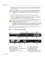
Page 40: ...d to help meet your network needs These switches provide a management platform and uplink to a network backbone for a stacked group of up to eight switches 1 High speed stacking cable 4 STACK DOWN con...

Page 41: ...sconnected from the stack The Console port on the manager switch remains active for out of band local switch management but the Console port on each member switch is deactivated This enables you to se...

Page 42: ...e becomes the Manager and all the next switches will join that stack regardless of Priority Firmware Revision or MAC Address The switches are assigned unit IDs in the order that you power on each swit...

Page 43: ...utlet and power cord are country dependent Important Considerations About Using Clear Config in a Stack When using the clear config command as described in the SecureStack C3 Configuration Guide to cl...

Page 44: ...conds for the switch to start up If the switch is a stack Manager it can take up to 3 minutes or more to start up depending on the number of Member switches in the stack 1 AC power cord 2 AC power con...

Page 45: ...e stack Manager The Manager LED on each Member switch will be off The hierarchy of the switches that will function as backup Manager is also determined in case the current Manager malfunctions is powe...

Page 46: ...ing a VT series emulation software package Using a DTE modem DB9 female to DB25 female cable you can connect products equipped with a DB9 DTE male console port to a VT series terminal or VT type termi...

Page 47: ...he switch If there is a switch designated as the Manager connect to its Console port 2 Plug the DB9 female connector at the other end of cable into the communications port on the PC 3 Turn on the PC a...

Page 48: ...ch If there is a switch designated as the Manager connect to its Console port 2 Plug the DB25 female connector at the other end of the cable into the port labeled COMM on the VT terminal 3 Turn on the...

Page 49: ...sole port 2 Plug the DB25 male connector at the other end of the cable into the modem communications port 3 Turn on the modem and make sure the remote modem is ON 4 With your PC connected to the remot...

Page 50: ...networking devices to these ports such as a bridge repeater or router use a crossover cable To connect twisted pair segments to the switch refer to Figure 3 13 and proceed as follows 1 Ensure that th...

Page 51: ...ht through cable is used to connect between switches or hub devices and an end user computer Refer to Figure 3 14 and Figure 3 15 for four wire RJ45 connections Refer to Figure 3 16 and Figure 3 17 fo...

Page 52: ...X 1 RJ45 switch port 3 RJ45 to RJ45 crossover cable 2 Other device port 4 RX RX and TX TX connections These connections must share a common color pair 1 RJ45 switch port 3 RJ45 to RJ45 straight throug...

Page 53: ...e RJ45 Pinouts for 10 100 1000BASE TX 1 RJ45 device port 3 RJ45 to RJ45 crossover cable 2 Other device port 1 RJ45 device port 3 RJ45 to RJ45 straight through cable 2 Other device port 3680 28 2 1 3 6...

Page 54: ...l instruments to view laser output The use of optical instruments to view laser output increases eye hazard Advertencia No utilizar instrumentos opticos para ver el laser El uso de instrumentos optico...

Page 55: ...sts by checking that the port Link Activity LED is on blinking green or solid green If the Link Activity LED is off perform the following steps until it is on a Verify that the device at the other end...

Page 56: ...of each strand of cable To connect an LC cable connector to a fixed LC connector of a Mini GBIC refer to Figure 3 19 and proceed as follows Warning Do not use optical instruments to view laser output...

Page 57: ...r end with two separate connectors one for each fiber optic strand In this case ensure that the transmit fiber optic strand is connected to the receive port and the receive fiber optic strand to the t...

Page 58: ...management from your local PC terminal or modem connection proceed as follows at the displayed startup screen 1 Enter rw Read Write for Username 2 At the Password prompt press Enter Return 3 For deta...

Page 59: ...location of LANVIEW LEDs on the C3G124 24P and C3G124 48P refer to Figure 4 1 and Figure 4 2 respectively These LEDs allow you to quickly observe network status for diagnosing switch and network prob...

Page 60: ...for redundant power source status 8 Link Activity LEDs for 1 Gbps Mini GBIC ports 21 through 241 1 These Mini GBIC ports will only establish a link when the RJ45 port equivalent is not linked on a C3G...

Page 61: ...ts 45 through 481 1 These Mini GBIC ports will only establish a link when the RJ45 port equivalent is not linked on a C3G124 48P For example when Mini GBIC port 45 is linked RJ45 port 45 is deactivate...

Page 62: ...ains red for several minutes the system may have a fatal error Contact Enterasys Networks for technical support Amber Solid Diagnostics are running If the LED remains amber for more than several minut...

Page 63: ...e RPS Off Connected C2RPS POE supply not in use Internal power supply failed None If a C2RPS POE RPS is connected to the switch it should be providing power To determine if there is a problem perform...

Page 64: ...iled 1 Check the attached powered device to see if it is defective 2 Internal power supply failed contact Enterasys Networks for technical support Blinking Port is linked and traffic is being received...

Page 65: ...mproper Console cable pinouts Refer to Appendix A for proper Console port pinouts Corrupt firmware image or hardware fault If possible attempt to download the image to the device again Refer to the Se...

Page 66: ...he type of STA Review the network design and delete unnecessary loops If the problem continues contact Enterasys Networks for technical support User parameters IP address device and module name etc we...

Page 67: ...ow logon to the switch through the Console port and assign a new password using the command line interface CLI 3 To access switch management from your local PC terminal or modem connection refer to th...

Page 68: ...Using the Reset Switch 4 10 Troubleshooting...

Page 69: ...thernet Specifications A 4 Console Port Pinout Assignments A 7 Regulatory Compliance A 7 Table A 1 C3G124 24P and C3G124 48P Specifications Item Specification C3G124 24P RJ45 ports 1 through 24 Twenty...

Page 70: ...rs Memory Processor MPC8245 400 MHz processor Dynamic Random Access Memory DRAM 256 MB FLASH Memory 64 MB Physical Dimensions 4 4 H x 44 1 W x 36 85 D cm 1 7 H x 17 4 W x 14 5 D in Approximate Weight...

Page 71: ...Storage Temperature 40 C to 70 C 40 F to 158 F Operating Relative Humidity 5 to 95 non condensing Table A 1 C3G124 24P and C3G124 48P Specifications continued Item Specification Table A 2 Mini GBIC In...

Page 72: ...th the 1000BASE T standard RJ45 connector Table A 2 Mini GBIC Input Output Port Specifications continued Item Specification Table A 3 MGBIC LC01 MGBIC MT01 Optical Specifications Item 62 5 m MMF 50 m...

Page 73: ...of the attached segment The Link Power Budget must not exceed those specified in this table The MGBIC LC03 input power must not exceed 3 dBm Otherwise saturation could occur 10 5 dB 10 5 dB Table A 6...

Page 74: ...mum cable length of the attached segment The Link Power Budget must not exceed those specified in this table The MGBIC 08 input power must not exceed 3 dBm Otherwise saturation could occur 23 dB 28 dB...

Page 75: ...ectromagnetic compatibility EMC requirements listed in Table A 12 1 Pin 2 Received Data input 3 Pin 5 Signal Ground 2 Pin 3 Transmitted Data output All other pins not connected 5 1 9 6 Table A 12 Comp...

Page 76: ...Regulatory Compliance A 8 Specifications...

Page 77: ...t conventions xv E Electromagnetic Compatibility EMC requirements A 7 F Fiber budget A 3 Front panel 1 2 1 4 H High speed stack connections introduction to 1 4 High speed stacking cables installation...

Page 78: ...ons A 1 C3G124 24P A 1 C3G124 48P A 2 MGBIC 02 A 6 MGBIC 08 A 6 MGBIC LC01 A 4 A 5 MGBIC LC03 A 5 MGBIC LC09 A 5 MGBIC MT01 A 4 A 5 Mini GBIC input outputs A 3 Specifications MGBIC LC01 optical A 6 St...

Reviews: