


Connecting AC and PoE Power
SecureStack B2 Installation Guide 3-15
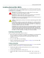
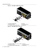
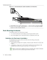
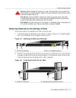
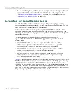
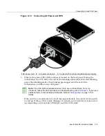
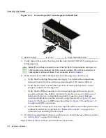
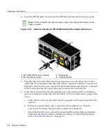
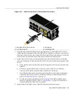
Figure 3-10 Connecting AC Power and RPS
3.
Observe
the
power
CPU
LED
(not
shown)
located
on
the
front
panel.
During
the
initialization,
the
CPU
LED
will
start
by
illuminating
solid
amber,
then
start
blinking
green,
then
blinking
amber,
then
blinking
green
again
until
the
end
of
the
initialization,
and
then
turns
solid
green.
If
the
switch
is
a
standalone
unit,
it
will
take
approximately
30 seconds
for
the
switch
to
start
up.
If
the
switch
is
a
stack
Manager,
it
can
take
up
to
3
minutes
or
more
to
start
up,
depending
on
the
number
of
Member
switches
in
the
stack.
1
AC power cord
2
AC power connector
3
Connector for external redundant power supply
Note:
If the CPU LED illuminates solid red, there was a critical failure. For more
information about the LED indications and troubleshooting, refer to
Chapter 4
. If you need
additional help, contact Enterasys Networks. Refer to “
Getting Help
” on page 1-8 for
details
.
Redu
ndan
t Pow
er Su
pply
DC L
ine -5
0V
/7.5A
MAX
,
+12V
/1
0.5A
MAX
AC L
INE
100-2
40 VA
C
50-60
Hz
7.5 A
MAX
MA
C A
DDR
ESS
SERIAL NO
.
STAC
K UP
STAC
K DO
WN
AC LINE
100-240
VAC
50-60 Hz
7.5 A MAX
À
Á
Â
Summary of Contents for SecureStack B2 B2G124-48P
Page 2: ......
Page 12: ...x ...
Page 21: ...x ...
Page 25: ...xiv ...
Page 29: ...Conventions Used in This Guide xviii About This Guide ...
Page 41: ...1000BASE T Network 2 4 Network Requirements ...
Page 81: ...Using the Reset Switch 4 10 Troubleshooting ...


