Attaching the Electrostatic Discharge Wrist Strap
3-14 Chassis Setup
5.
Torque
screws
to
67
inch
pounds
(±
5%).
National
Deviations:
•
In
Norway,
Sweden,
and
Finland,
the
same
procedure
can
be
used
for
a
permanent
protective
earth
ground
connection
as
required
by
their
national
deviation
to
IEC
60950,
Section
5.1.7.
•
In
Denmark,
the
chassis
must
be
installed
utilizing
a
Type
B
grounded
plug.
Attaching the Electrostatic Discharge Wrist Strap
The
Electrostatic
Discharge
(ESD)
wrist
strap
must
be
attached
before
handling
the
power
supplies,
fan
tray,
and
modules
used
in
the
S8
chassis.
In
addition,
observe
all
precautions
when
handling
these
modules
to
prevent
damage
from
electrostatic
discharge.
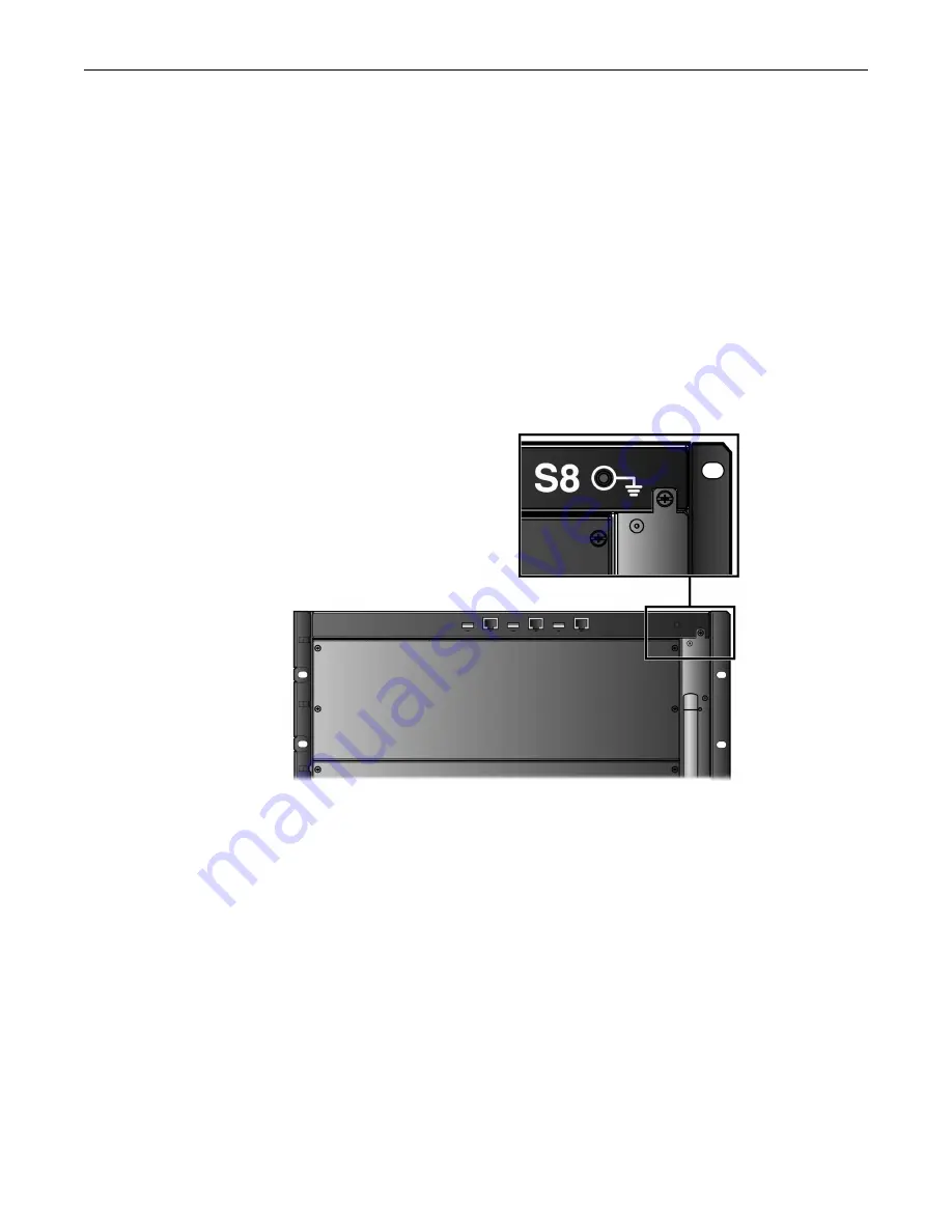
Place
the
ESD
wrist
strap
on
your
wrist
and
plug
the
other
end
into
the
grounding
receptacle,
at
the
top
right
corner
of
the
chassis,
shown
in
.
Figure 3-11 ESD Grounding Receptacle
Installing and Removing an S-AC-PS Power Supply
S
‐
AC
‐
PS
power
supplies
provide
two
power
output
levels
relative
to
the
input
power
source.
The
power
supplies
draw
either
110
Vac
12A
or
220
Vac
6A
service,
providing
1200
or
1600
watts
per
power
supply,
depending
upon
the
electrical
infrastructure
of
the
site
where
the
S8
chassis
will
be
located.
Each
S
‐
AC
‐
PS
power
supply
requires
a
dedicated
100
‐
240
Vac,
20
Amp
earth
‐
grounded
circuit.
Power
cords
shipped
with
this
unit
are
country
‐
dependent.
Each
power
cord
must
be
plugged
into
an
independent
power
circuit.
As
you
add
modules
to
the
S8
chassis,
you
may
be
required
to
install
more
power
supplies.
Additional
power
supplies
can
be
installed
to
provide
redundancy.
This
would
require
incremental
power
be
added
to
the
base
power
requirements
of
the
chassis
and
its
components,
depending
on
the
power
redundancy
you
want
to
support.
In
a
redundant
power
configuration,
when
at
least
two
power
supplies
are
installed,
the
power
from
each
is
evenly
distributed.
If
one
power
supply
fails,
the
second
power
supply
assumes
the
load.
Additional
modules
share
the
load
as
required.
Summary of Contents for S4-Chassis
Page 2: ......
Page 12: ...x...
Page 16: ...xiv...
Page 20: ...Getting Help xviii About This Guide...
Page 28: ...Features 1 8 Introduction...
Page 62: ...Completing the Installation 3 32 Chassis Setup...


