background image

Sensitivity

C-5

Sensitivity

IEEE 802.11a

Sensitivity (GHz - dBm)

Modulation/Rates

5.15-5.250

5.25-5.350

5.50-5.700

5.725-5.825

BPSK (6 Mbps)

-88

-88

-88

-88

BPSK (9 Mbps)

-87

-87

-87

-87

QPSK (12 Mbps)

-86

-86

-86

-86

QPSK (18 Mbps)

-83

-83

-83

-83

16 QAM (24 Mbps)

-80

-80

-80

-80

16 QAM (36 Mbps)

-76

-76

-76

-76

64 QAM (48 Mbps)

-73

-73

-73

-73

64 QAM(54 Mbps)

-70

-70

-70

-70

IEEE 802.11g

Data Rate

Sensitivity (dBm) 

6 Mbps

-88

9 Mbps

-86

12 Mbps

-85

17 Mbps

-84

24 Mbps

-80

36 Mbps

-76

48 Mbps

-73

54 Mbps

-70

IEEE 802.11b

Data Rate

Sensitivity (dBm) 

1 Mbps

-90

2 Mbps

-89

5.5 Mbps

-87

11 Mbps

-85

Summary of Contents for RoamAbout RBT-4102-BG

Page 1: ...P N 9034148 14 RoamAbout RBT 4102 RBT 4102 BG and RBT 4102 EU Wireless Access Point Installation Guide ...

Page 2: ......

Page 3: ...ys Networks Inc 50 Minuteman Road Andover MA 01810 2006 Enterasys Networks Inc All rights reserved Part Number 9034148 14 June 2006 ENTERASYS ENTERASYS NETWORKS ENTERASYS ROAMABOUT LANVIEW NETSIGHT ROAMABOUT WEBVIEW and any logos associated therewith are trademarks or registered trademarks of Enterasys Networks Inc in the United States and other countries All other product names mentioned in this ...

Page 4: ... void the user s authority to operate this equipment This device complies with Part 15 of the FCC Rules Operation is subject to the following two conditions 1 This device may not cause harmful interference and 2 this device must accept any interference received including interference that may cause undesired operation IEEE 802 11b or 802 11g operation of this product in the U S A is firmware limit...

Page 5: ...s 1 This device may not cause interference and 2 This device must accept any interference including interference that may cause undesired operation of the device This device has been designed to operate with an antenna having a maximum gain of 23 dB Antenna having a higher gain is strictly prohibited per regulations of Industry Canada The required antenna Impedance is 50 ohms To reduce potential r...

Page 6: ...o other system The user is obligated to ensure the device is operating according to the channel limitations indoor outdoor restrictions and license requirements for each European Community country as described in this document This device employs a radar detection feature required for European Community operation in the 5 GHz band This feature is automatically enabled when the country of operation...

Page 7: ...vice This device will automatically limit the allowable channels determined by the current country of operation Incorrectly entering the country of operation may result in illegal operation and may cause harmful interference to other system The user is obligated to ensure the device is operating according to the channel limitations indoor outdoor restrictions and license requirements for each coun...

Page 8: ...ast Community The user installer must use the provided configuration utility to check the current channel of operation and make necessary configuration changes to ensure operation occurs in conformance with the spectrum usage laws as described below and elsewhere in this document EC Konformitätserklärung Die Kennzeichnung mit dem obigen Symbol zeigt die Übereinstimmung mit den wichtigen Anforderun...

Page 9: ...nnungsfunktion die für den Betrieb im 5 GHz Band in der Europäischen Gemeinschaft erforderlich ist Diese Funktion wird automatisch aktiviert wenn für das Land der Europäischen Gemeinschaft die Betriebslandeinstellung richtig konfiguriert wurde Ein Radarbetrieb in der Nähe kann zu einer vorübergehenden Betriebsunterbrechung dieses Geräts führen Die Radarerkennungsfunktion sorgt dafür dass das Gerät...

Page 10: ...n Not Allowed None Griechenland Ungarn Der Betrieb in den Bändern 5 15 5 35 GHz ist im Freien nicht zulässig Kanäle 36 64 English Hereby Enterasys declares that this Radio LAN device is in compliance with the essential requirements and other relevant provisions of Directive 1999 5 EC A copy of the original Declaration of conformity can be obtained from Enterasys Networks 50 Minuteman Road Andover ...

Page 11: ... der ursprünglichen Erklärung der Übereinstimmung kann von erhalten werden Enterasys Networks 50 Minuteman Road Andover Ma 01810 USA Greek GR με την παρουσα Enterasys δηλωνει οτι radio LAN device συμμορφωνεται προσ τισ ουσιωδεισ απαιτησεισ και τισ λοιπεσ σΧετικεσ διαταξεισ τησ οδηγιασ 1999 5 εκ Ένα αντίγραφο της αρχικής Διακήρυξης της συμμόρφωσης μπορεί να ληφθεί από Enterasys Networks 50 Minutema...

Page 12: ...guration for mating with an EN 60320 IEC 320 appliance inlet The socket outlet must be near to the unit and easily accessible You can only remove power from the unit by disconnecting the power cord from the outlet This unit operates under SELV Safety Extra Low Voltage conditions according to IEC 60950 The conditions are only maintained if the equipment to which it is connected also operates under ...

Page 13: ... de l appareil et son accès doit être facile Vous ne pouvez mettre l appareil hors circuit qu en débranchant son cordon électrique au niveau de cette prise Power Cord Set U S A and Canada The cord set must be UL approved and CSA certified The minimum specifications for the flexible cord are No 18 AWG not longer than 2 meters or 16 AWG Type SV or SJ 3 conductor The cord set must have a rated curren...

Page 14: ...Steckdose angeschlossen werden welche die internationalen Sicherheitsnormen erfüllt Der Gerätestecker der Anschluß an das Gerät nicht der Wandsteckdosenstecker muß einen gemäß EN 60320 IEC 320 konfigurierten Geräteeingang haben Cordon électrique Il doit être agréé dans le pays d utilisation Etats Unis et Canada Le cordon doit avoir reçu l homologation des UL et un certificat de la CSA Les spe cifi...

Page 15: ...A und Kanada Der Cord muß das UL gepruft und war das CSA beglaubigt Das Minimum spezifikation fur der Cord sind Nu 18 AWG nicht mehr als 2 meter oder 16 AWG Der typ SV oder SJ 3 Leiter Der Cord muß haben eine strombelastbarkeit aus wenigstens 10 A Dieser Stromstecker muß hat einer erdschluss mit der typ NEMA 5 15P 15A 125V oder NEMA 6 15P 15A 250V konfiguration Danemark Dieser Stromstecker muß die...

Page 16: ...pment is required and that this product was placed on the European market after August 13 2005 the date of enforcement for Directive 2002 96 EC 2 When this product has reached the end of its serviceable life it cannot be disposed of as unsorted municipal waste It must be collected and treated separately 3 It has been determined by the European Parliament that there are potential negative effects o...

Page 17: ...ALF OF THE END USER IF THE END USER IS AN ENTITY ON WHOSE BEHALF YOU ARE AUTHORIZED TO ACT YOU AND YOUR SHALL BE DEEMED TO REFER TO SUCH ENTITY AND THAT YOU AGREE THAT YOU ARE BOUND BY THE TERMS OF THIS AGREEMENT WHICH INCLUDES AMONG OTHER PROVISIONS THE LICENSE THE DISCLAIMER OF WARRANTY AND THE LIMITATION OF LIABILITY IF YOU DO NOT AGREE TO THE TERMS OF THIS AGREEMENT OR ARE NOT AUTHORIZED TO EN...

Page 18: ...m is exported from the United States pursuant to the License Exception TSR under the U S Export Administration Regulations in addition to the restriction on transfer set forth in Sections 1 or 2 of this Agreement You agree not to i reexport or release the Program the source code for the Program or technology to a national of a country in Country Groups D 1 or E 2 Albania Armenia Azerbaijan Belarus...

Page 19: ...GHTS GRANTED HEREIN 8 AUDIT RIGHTS You hereby acknowledge that the intellectual property rights associated with the Program are of critical value to Enterasys and accordingly You hereby agree to maintain complete books records and accounts showing i license fees due and paid and ii the use copying and deployment of the Program You also grant to Enterasys and its authorized representatives upon rea...

Page 20: ...the benefit of the parties their legal representatives permitted transferees successors and assigns as permitted by this Agreement Any attempted assignment transfer or sublicense in violation of the terms of this Agreement shall be void and a breach of this Agreement 12 WAIVER A waiver by Enterasys of a breach of any of the terms and conditions of this Agreement must be in writing and will not be ...

Page 21: ...uired Connections 3 1 Logging In 3 2 Using Web Management 3 6 Chapter 4 Network Configuration Network Topologies 4 2 Ad Hoc Wireless LAN no Access Point 4 2 Infrastructure Wireless LAN 4 3 Infrastructure Wireless LAN for Roaming Wireless PCs 4 4 Infrastructure Wireless Bridge 4 5 Appendix A Troubleshooting Diagnosing Access Point Indicators A 1 Appendix B Cables and Pinouts Twisted Pair Cable Assi...

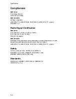
Page 22: ...tion Type C 2 Network Configuration C 2 Operating Frequency C 2 AC Power Adapter C 2 Unit Power Supply C 2 PoE DC C 2 Physical Size C 2 Weight C 3 LED Indicators C 3 Network Management C 3 Temperature C 3 Humidity C 3 Compliances C 4 Radio Signal Certification C 4 Safety C 4 Standards C 4 Sensitivity C 5 Transmit Power C 6 Operating Range C 7 External Antennas C 8 Index ...

Page 23: ...alling the RoamAbout Wireless Access Point Associated Documents You can download the documentation from the Enterasys Networks web site http www enterasys com products wireless RoamAbout RBT 4102 Wireless Access Point Configuration Guide This document provides the information to configure and manage the RBT 4102 Wireless Access Point RoamAbout RBT 4102 RBT 1602 Wireless Access Point Antenna Site P...

Page 24: ...k load and frame size at the time of trouble if known The device history for example have you returned the device before is this a recurring problem Any previous Return Material Authorization RMA numbers World Wide Web http www enterasys com services support Phone 1 800 872 8440 toll free in the U S and Canada or 1 978 684 1000 For the Enterasys Networks Support toll free number in your country ht...

Page 25: ...ients in the service area Bridge Point to Point Providing links to other access points in Bridge or Root Bridge mode connecting wired LAN segments Root Bridge Point to Multipoint Providing links to other access points in Bridge mode connecting wired LAN segments Only one unit in the wireless bridge network can be set to Root Bridge mode In addition the access point offers full network management c...

Page 26: ...ezel Mounting bracket Documentation CD includes the Installation Guide and the Configuration Guide Inform your dealer if there are any incorrect missing or damaged parts If possible retain the carton including the original packing materials Use them again to repack the product in case there is a need to return it Caution The Bezel should not be used in a plenum area Hardware Description Top Panel ...

Page 27: ...Hardware Description 1 3 Rear Panel Security Slot Console Port RJ 45 Port PoE Connector Reset Button External Antenna Connector 802 11b g Radio DC Power Supply External Antenna Connector 802 11a Radio ...

Page 28: ...on page 2 3 External Antenna Connectors The access point supports external antenna connections for both the 2 4 GHz and 5 GHz radios These antennas offer a variety of options for extending the radio range and shaping the coverage area For a list of external antennas their model type and gain refer to External Antennas on page C 8 For information on the external antennas available refer to the Roam...

Page 29: ...rnet node and performs a bridging function by moving packets from the wired LAN to remote workstations on the wireless infrastructure Note The RJ 45 port also supports Power over Ethernet PoE based on the IEEE 802 3af standard Refer Power Connector on page 1 6 for information on supplying power to the access point s network port from a network device such as a switch that provides Power over Ether...

Page 30: ...wer switch It is powered on when connected to the AC power adapter and the power adapter is connected to a power source The power adapter automatically adjusts to any voltage between 100 240 volts at 50 or 60 Hz No voltage range settings are required The access point may also receive Power over Ethernet PoE from a switch or other network device that supplies power over the network cable based on t...

Page 31: ...ay cause reduced signal or null zones in parts of the coverage area Mount away from any signal absorbing or reflecting structures such as those containing metal 2 Mount the Access Point The access point can be mounted on any flat surface such as a desktop a ceiling or a wall Mounting on a flat surface other than wall or ceiling To keep the access point from sliding on the surface attach the four r...

Page 32: ...mly to the wall or ceiling Attach the access point to the mounting bracket Line up the two mounting points on the access point with the two mounting slots on the bracket see the following figure Place the mounting points of the access point into the mounting slots of the bracket slide it into position so that the bracket fastening screw on the access point lines up with the tab on the bracket Then...

Page 33: ... to a 10 100 Mbps Ethernet through a network device such as a hub or a switch Connect your network to the RJ 45 port on the back panel with category 3 or 4 UTP Ethernet cable When the access point and the connected device are powered on the Ethernet Link LED should light indicating a valid network connection Note The RJ 45 port on the access point supports automatic MDI MDI X operation so you can ...

Page 34: ...Hardware Installation 2 4 ...

Page 35: ...gement Using the CLI Required Connections The access point provides an RS 232 serial port that enables a connection to a PC or terminal for monitoring and configuration Attach a VT100 compatible terminal or a PC running a terminal emulation program to the access point You can use the console cable provided with this package or use a cable that complies with the wiring assignments To connect to the...

Page 36: ...ccess Point 4102 CLI prompt appears Note The access point requests an IP address from a Dynamic Host Configuration Protocol DHCP server by default If a DHCP server does not respond then the access point uses the default address 192 168 1 1 which may not be compatible with your network To assign an IP address you must use the CLI Go to Step 3 2 If applicable set the Country Code This restricts oper...

Page 37: ...EORGIA DE GERMANY GR GREECE GT GUATEMALA HN HONDURAS HK HONG KONG HU HUNGARY IS ICELAND IN INDIA ID INDONESIA IR IRAN IE IRELAND IL ISRAEL IT ITALY JP JAPAN JO JORDAN KZ KAZAKHSTAN KP NORTH KOREA KR KOREA REPUBLIC KU KUWAIT LV LATVIA LB LEBANON LI LIECHTENSTEIN LT LITHUANIA LU LUXEMBOURG MO MACAU MK MACEDONIA MY MALAYSIA MT MALTA MC MONACO MA MOROCCO NL NETHERLANDS NZ NEW ZEALAND NO NORWAY OM OMAN...

Page 38: ...rk e Go to Step 4 4 Change the default username and password Enter username and specify a unique user name enter password and specify a unique password RoamAbout 4102 if ethernet no ip dhcp DHCP client state has changed Please reset AP for change to take effect RoamAbout 4102 if ethernet exit RoamAbout 4102 reset board Reboot system now y n y Username admin Password RoamAbout 4102 configure Enter ...

Page 39: ... and so forth VLAN management is enabled by default and cannot be disabled Note You must set up the network switch port to support tagged VLAN packets from the access point The switch port must also be configured to accept the access point s management VLAN ID and native VLAN IDs 6 Refer to the RoamAbout RBT 4102 Wireless Access Point Configuration Guide for advanced configuration RoamAbout 4102 c...

Page 40: ... If your access point uses a DHCP assigned IP address make sure the access point is connected to your network and enter the DHCP assigned IP address in your browser s address field Use your DHCP server or other utility to determine the access point s IP address If your access point uses a static IP address connect a system to the access point s Ethernet port and enter the default IP address http 1...

Page 41: ... the Country Code a Click the arrow in the Country pull down menu to select the appropriate country then click Apply at the bottom of the page b Click Administration from the menu on the left hand side of the page The Administration page appears ...

Page 42: ...cated at the bottom of the page The access point prompts you to confirm that you want to reboot the system d Click OK The access point reboots and the Login window appears e Enter the username admin and the password password and click LOGIN The Identification page appears f Go to step 4 ...

Page 43: ...ngth 1 to 22 characters System Location is a text string that describes the system location Maximum length 253 characters System Contact is a text string that describes the system contact Maximum length 253 characters The access point displays a Settings Saved message Click OK 5 To set a static IP address a Click TCP IP Settings from the menu on the left hand side of the page The TCP IP Settings p...

Page 44: ... Default Enable c Enter the IP Address Subnet Mask Default Gateway and Primary and Secondary DNS Note Enterasys Networks recommends that you reset the access point after changing the DHCP client status IP Address is the IP address of the access point Valid IP addresses consist of four decimal numbers 0 to 255 separated by periods Subnet Mask is the mask that identifies the host address bits used f...

Page 45: ... of the page The Administration page appears g Click the Reset button next to Reset Access Point located at the bottom of the page The access point prompts you to confirm that you want to reboot the system h Click OK The access point reboots i Type the IP address that you specified for the access point in your browser s address field For example enter http 10 2 101 22 The Login window appears j En...

Page 46: ...eft hand side of the page The Administration page appears b Specify a new username in the Username field c Specify a new password in the Password field d Specify the new password again in the Confirm Password field e Click Apply at the bottom of the page The access point displays a Settings Saved message f Click OK ...

Page 47: ...d with the specified VLAN to manage the access point via remote management SSH SNMP Telnet and so forth VLAN management is enabled by default and cannot be disabled Note You must set up the network switch port to support tagged VLAN packets from the access point The switch port must also be configured to accept the access point s management VLAN ID and native VLAN IDs c Click Apply at the bottom o...

Page 48: ...Access Point Configuration 3 14 ...

Page 49: ...s LAN for roaming wireless PCs Infrastructure wireless bridge to connect wired LANs The 802 11b and 802 11g frequency band which operates at 2 4 GHz can easily encounter interference from other 2 4 GHz devices such as other 802 11b or 802 11g wireless devices cordless phones and microwave ovens If you experience poor wireless LAN performance try the following measures Limit any possible sources of...

Page 50: ...ireless adapter connected via radio signals as an independent wireless LAN Computers in a specific ad hoc wireless LAN must therefore be configured to the same radio channel An ad hoc wireless LAN can be used for a branch office or SOHO operation Ad Hoc Wireless LAN Notebook with Wireless USB Adapter Notebook with Wireless PC Card PC with Wireless PCI Adapter ...

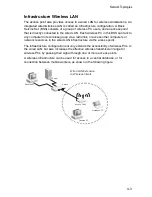
Page 51: ...group via a radio link or access other computers or network resources in the wired LAN infrastructure via the access point The infrastructure configuration not only extends the accessibility of wireless PCs to the wired LAN but also increases the effective wireless transmission range for wireless PCs by passing their signal through one or more access points A wireless infrastructure can be used fo...

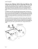
Page 52: ...ccess points The SSID can be manually configured by the clients can be detected in an access point s beacon or can be obtained by querying for the identity of the nearest access point For clients that do not need to roam set the SSID for the wireless card to that used by the access point to which you want to connect A wireless infrastructure can also support roaming for mobile workers More than on...

Page 53: ...work One unit only must be configured as the root bridge in the wireless network The root bridge should be the unit connected to the main core of the wired LAN Other bridges must configure one parent link to the root bridge or to a bridge connected to the root bridge The other five available WDS links can be specified as child links to other bridges This forms a tiered star topology for the wirele...

Page 54: ...Network Configuration 4 6 ...

Page 55: ...ff the port power Power LED is Amber The access point has detected a system error Reboot the access point to try and clear the condition If the condition does not clear contact your local dealer for assistance Ethernet Link LED is Off Verify that the access point and attached device are powered on Be sure the cable is plugged into both the access point and corresponding device Verify that the prop...

Page 56: ...Troubleshooting A 2 ...

Page 57: ... connectors that conform with FCC standards The following figure illustrates how the pins on the RJ 45 connector are numbered Be sure to hold the connectors in the same orientation when attaching the wires to the pins 10 100BASE TX Pin Assignments Use unshielded twisted pair UTP or shielded twisted pair STP cable for RJ 45 connections 100 ohm Category 3 or better cable for 10 Mbps connections Also...

Page 58: ...ng power Negative Vport Receive Data plus RD and GND Positive Vport 4 GND Positive Vport 48V feeding power Negative Vport 5 GND Positive Vport 48V feeding power Negative Vport 6 Transmit Data minus TD and 48V feeding power Negative Vport Receive Data minus RD and GND Positive Vport 7 48V feeding power Negative Vport GND Positive Vport 8 48V feeding power Negative Vport GND Positive Vport Note The ...

Page 59: ...int is used to connect to the access point for out of band console configuration The command line configuration program can be accessed from a terminal or a PC running a terminal emulation program The pin assignments and cable wiring used to connect to the console port are provided in the following table White Orange Stripe Orange White Green Stripe 1 2 3 4 5 6 7 8 1 2 3 4 5 6 7 8 EIA TIA 568B RJ ...

Page 60: ...tch s 9 Pin Serial Port Null Modem PC s 9 Pin DTE Port 2 RXD RXD 3 TxD 3 TXD TXD 2 RxD 5 SGND SGND 5 SGND Note he left hand column pin assignments are for the male DB 9 connector on the access point Pin 3 TXD or transmit data must emerge on the management console s end of the connection as RXD receive data ...

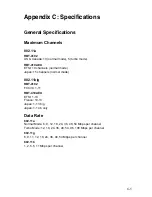
Page 61: ...els normal mode Japan 15 channels normal mode 802 11b g RBT 4102 FCC IC 1 11 RBT 4102 EU ETSI 1 13 France 10 13 Japan 1 13 b g Japan 1 14 b only Data Rate 802 11a Normal Mode 6 9 12 18 24 36 48 54 Mbps per channel Turbo Mode 12 18 24 36 48 54 96 108 Mbps per channel 802 11g 6 9 11 12 18 24 36 48 54 Mbps per channel 802 11b 1 2 5 5 11 Mbps per channel ...

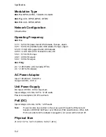
Page 62: ... 04 5 08 GHz Japan 802 11b g 2 4 2 4835 GHz US Canada ETSI 2 4 2 497 GHz Japan AC Power Adapter Input 100 240 AC 50 60 Hz Output 48 VDC 0 38 A Unit Power Supply DC Input 48 VDC 0 38 A maximum Input voltage 48 volts 0 27 A 12 95 watts Power consumption 9 6 W maximum PoE DC Input voltage 48 volts 0 27A 12 95 watts Note Power can also be provided to the access point through the Ethernet port based on...

Page 63: ...LED Indicators Power Ethernet Link Activity 11a and 11g Wireless Link Activity Network Management Web browser RS232 console Telnet SSH SNMP Temperature Operating 5 C to 50 C 23 F to 122 F Storage 0 C to 70 C 32 F to 158 F Humidity 15 to 95 non condensing ...

Page 64: ... 247 15 207 2 4 GHz FCC Part 15E 15 407 5 GHz RSS 210 Canada RBT 4102 EU EN55022 1998 EN55024 1998 EN61000 3 2 2000 EN61000 3 3 1995 EN 301 893 EN 300 328 EN 301 489 1 EN 301 489 17 ARB STD T70 ARB STD 66 RCR STD 33 ARB STD T71 Japan Safety UL CUL CSA 22 2 No 60950 1 UL60950 1 EN60950 1 TÜV GS EN60601 IEC60950 1 CB EN60601 RBT 4102 EU PoE only Standards IEEE 802 3 10BASE T IEEE 802 3u 100BASE TX I...

Page 65: ... 87 QPSK 12 Mbps 86 86 86 86 QPSK 18 Mbps 83 83 83 83 16 QAM 24 Mbps 80 80 80 80 16 QAM 36 Mbps 76 76 76 76 64 QAM 48 Mbps 73 73 73 73 64 QAM 54 Mbps 70 70 70 70 IEEE 802 11g Data Rate Sensitivity dBm 6 Mbps 88 9 Mbps 86 12 Mbps 85 17 Mbps 84 24 Mbps 80 36 Mbps 76 48 Mbps 73 54 Mbps 70 IEEE 802 11b Data Rate Sensitivity dBm 1 Mbps 90 2 Mbps 89 5 5 Mbps 87 11 Mbps 85 ...

Page 66: ...20 20 19 36 Mbps 20 20 19 19 48 Mbps 19 19 18 18 54 Mbps 18 18 17 16 IEEE 802 11g Maximum Output Power GHz dBm Data Rate 2 412 2 417 2 467 2 472 6 Mbps 20 20 20 9 Mbps 20 20 20 12 Mbps 20 20 20 18 Mbps 20 20 20 24 Mbps 20 20 20 36 Mbps 20 20 20 48 Mbps 20 20 20 54 Mbps 19 19 19 IEEE 802 11b Maximum Output Power GHz dBm Data Rate 2 412 2 417 2 467 2 472 1 Mbps 20 20 20 2 Mbps 20 20 20 5 5 Mbps 20 2...

Page 67: ... ft 1 A typical indoor environment office or home with floor to ceiling obstructions between the access point and clients 802 11g Wireless Distance Table Speed and Distance Ranges1 54 Mbps 48 Mbps 36 Mbps 24 Mbps 18 Mbps 12 Mbps 11 Mbps 9 Mbps 6 Mbps 5 Mbps 2 Mbps 1 Mbps 20 m 66 ft 25 m 82 ft 35 m 115 ft 43 m 141 ft 50 m 164 ft 57 m 187 ft 66 m 216 ft 71 m 233 ft 80 m 262 ft 85 m 279 ft 90 m 295 f...

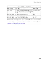
Page 68: ...1 dBi with 8 ft cable RBTES BG M08M 2 4 2 5 GHz Omnidirectional outdoor 8 dBi RBTES BG S1490M 2 4 2 5 GHz Sector Panel outdoor 14 dBi 90 RBTES BG P18M 2 4 2 5 GHz Directional Panel outdoor 18 dBi RBTES AM M10M 5 125 5 35 GHz Omnidirectional outdoor 10 dBi RBTES AW S1590M 4 9 GHz Adjustable Sector outdoor 5 25 5 35 GHz Adjustable Sector outdoor 5 4 5 7 GHz Adjustable Sector outdoor 15 dBi 90 15 dBi...

Page 69: ...sys com products wireless Japan External Antenna Configurations Antenna Model Antenna Type Antenna Gain RBT4K AG IA 2 4 2 5 GHz Omnidirectional Indoor Range Extender 5 15 5 35 GHz Omnidirectional Indoor Range Extender 5 725 5 825 GHz Omnidirectional Indoor Range Extender 1 dBi with 8 ft cable RBTES BG M08M 2 4 2 5 GHz Omnidirectional outdoor 8 dBi RBTES BG S1490M 2 4 2 5 GHz Sector Panel outdoor 1...

Page 70: ...Specifications C 10 ...

Page 71: ...3 4 logging in 3 2 VLAN management 3 5 console port 1 5 connecting 2 3 pin assignments B 3 country codes 3 3 CSMA CA 1 1 D data rate options C 1 default password CLI 3 1 web management 3 6 default username CLI 3 1 web management 3 6 DHCP 3 10 disable DHCP web management 3 9 documentation location xxi E Ethernet cable 2 3 port 1 5 G Gateway address 3 10 getting help xxii H help xxii I IEEE 802 11a ...

Page 72: ...cations C 2 power connection 2 3 Power over Ethernet See PoE power supply specifications C 2 R reset button 1 6 S set username and password web management 3 12 specifications C 1 subnet mask 3 10 system location 3 9 length 3 9 system name 3 9 length 3 9 T technical support xxii troubleshooting A 1 U using the CLI 3 1 V VLAN management web management 3 13 W web management 3 6 country code 3 7 loggi...

Reviews: