background image

UNCONTROLLED COPY WHEN DOWNLOADED OR PRINTED


Enstrom TH-28/480 Series Maintenance Manual Supplement 8 


G1000H Integrated Flight Deck System 


Diagram 1-1. G1000H Power Distribution Interface 

(Ref. 4192805-1 Rev. A) (Sheet 2 of 2) 


Rev. 1, Jan 25/18 


Page 1-57 (1-58 Blank) 

Visit www.enstromhelicopter.com for instructions to order an original manual and to register for email notification of updates.

Summary of Contents for TH-28/480 Series

Page 1: ...inspections and other maintenance required under 14 CFR 43 16 and 91 403 of the Federal Aviation Regulations unless an alternative program has been FAA approved Copyright 2014 2018 by The Enstrom Helicopter Corporation 2209 22nd Street Menominee Michigan 49858 3515 Telephone 906 863 1200 Fax 906 863 6821 Visit www enstromhelicopter com for instructions to order an original manual and to register f...

Page 2: ...TH 28 480 Series Maintenance Manual Supplement 8 G1000H Integrated Flight Deck System May 14 14 Page ii INTENTIONALLY LEFT BLANK Visit www enstromhelicopter com for instructions to order an original manual and to register for email notification of updates ...

Page 3: ... opinion of the user any information has been omitted or requires clarification please direct your comments to Enstrom via this form duplicate or other similar form Send the recommended changes to The Enstrom Helicopter Corporation 2209 22nd Street Menominee MI 49858 3515 ATTN Technical Publications Manual Identification Enstrom TH 28 480 Series Maintenance Manual Supplement 8 G1000H Integrated Fl...

Page 4: ...TH 28 480 Series Maintenance Manual Supplement 8 G1000H Integrated Flight Deck System May 14 14 Page iv INTENTIONALLY LEFT BLANK Visit www enstromhelicopter com for instructions to order an original manual and to register for email notification of updates ...

Page 5: ...t 8 G1000H Integrated Flight Deck System Rev 1 Jan 25 18 Page v RECORD OF REVISIONS REV ISSUE DATE DATE INSERTED BY REV ISSUE DATE DATE INSERTED BY 1 Jan 25 18 Jan 25 18 JW Visit www enstromhelicopter com for instructions to order an original manual and to register for email notification of updates ...

Page 6: ...TH 28 480 Series Maintenance Manual Supplement 8 G1000H Integrated Flight Deck System May 14 14 Page vi INTENTIONALLY LEFT BLANK Visit www enstromhelicopter com for instructions to order an original manual and to register for email notification of updates ...

Page 7: ...vionics Unit 1 6 GEA 71H Engine Aircraft I O Unit 1 7 ST 32 Signal Conditioners 1 7 GTX 33H w ES Transponder 1 7 GRS 77H AHRS with GMU 44 Magnetometer 1 8 GDC 74H Air Data Computer with GTP 59 OAT Probe 1 9 Caution and Warning System 1 11 CMC Data Logging 1 11 Vendor Publications 1 12 G1000H Software Versions 1 13 Airworthiness Limitations 1 14 Servicing Troubleshooting and Periodic Inspection 1 1...

Page 8: ... 2 3 Servicing Troubleshooting and Periodic Inspections 2 3 2 3 1 Servicing 2 3 2 3 2 Troubleshooting 2 3 2 3 3 Periodic Inspections 2 3 2 4 System Maintenance GTS 800 2 4 2 4 1 Scheduled Maintenance 2 4 2 4 2 Removal 2 4 2 4 3 Installation 2 4 3 1 System Description 3 1 3 1 1 Vendor Publications 3 1 3 2 Airworthiness Limitations 3 2 3 3 Servicing Troubleshooting and Periodic Inspections 3 3 3 3 1...

Page 9: ... 4 4 1 Scheduled Maintenance 4 4 4 4 2 Removal 4 4 4 4 3 Installation 4 4 5 1 System Description 5 1 5 1 1 Vendor Publications 5 1 5 2 Airworthiness Limitations 5 2 5 3 Servicing Troubleshooting and Periodic Inspections 5 3 5 3 1 Servicing 5 3 5 3 2 Troubleshooting 5 3 5 3 3 Periodic Inspections 5 3 5 4 System Maintenance KN 63 5 4 5 4 1 Scheduled Maintenance 5 4 5 4 2 Removal 5 4 5 4 3 Installati...

Page 10: ... Removal 1 28 Figure 19 Shroud Installation 1 30 Figure 20 PFD MFD Cooling Fan Installation 1 31 Figure 21 GIA 63H Installation and Removal 1 31 Figure 22 GRS 77H 1 34 Figure 23 GRS 77H Installation 1 34 Figure 24 GMU 44 Installation and Removal 1 36 Figure 25 GDC 74H Installation and Removal 1 38 Figure 26 GEA 71H Installation and Removal 1 40 Figure 27 GTX 33H Installations and Removal 1 40 Figu...

Page 11: ...1000H Exterior Lighting Interface 1 89 Diagram 1 7 G1000H Hour Meter Interface 1 91 Diagram 1 8 G1000H Day Night Annunciator Dimmer Interface 1 93 Diagram 1 9 G1000H Power Distribution Interface 1 95 Diagram 1 10 G1000H Interface 1 99 Diagram 1 11 G1000H Ground Interface 1 119 Diagram 1 12 G1000H Interior Lighting Interface 1 121 Diagram 2 1 GTS 800 Traffic Advisory System Interface 2 9 Diagram 3 ...

Page 12: ...8 480 Series Maintenance Manual Supplement 8 G1000H Integrated Flight Deck System Rev 1 Jan 25 18 Page xii INTENTIONALLY LEFT BLANK Visit www enstromhelicopter com for instructions to order an original manual and to register for email notification of updates ...

Page 13: ...14 1 23 May 14 14 1 24 May 14 14 1 25 Jan 25 18 1 26 May 14 14 1 27 Jan 25 18 1 28 May 14 14 1 29 Jan 25 18 1 30 Jan 25 18 1 31 May 14 14 1 32 Jan 25 18 1 33 Jan 25 18 1 34 May 14 14 1 35 Jan 25 18 1 36 May 14 14 1 37 Jan 25 18 1 38 May 14 14 1 39 Jan 25 18 1 40 May 14 14 1 41 Jan 25 18 1 42 Jan 25 18 1 43 Jan 25 18 1 44 May 14 14 1 45 May 14 14 1 46 May 14 14 1 47 May 14 14 1 48 May 14 14 1 49 Ma...

Page 14: ...18 1 109 Jan 25 18 1 110 Jan 25 18 1 111 Jan 25 18 1 112 Jan 25 18 1 113 Jan 25 18 1 114 Jan 25 18 1 115 Jan 25 18 1 116 Jan 25 18 1 117 Jan 25 18 1 118 Jan 25 18 1 119 Jan 25 18 1 120 Jan 25 18 1 121 Jan 25 18 1 122 Jan 25 18 2 1 Jan 25 18 2 2 May 14 14 2 3 May 14 14 2 4 May 14 14 2 5 May 14 14 2 6 May 14 14 2 7 May 14 14 2 8 May 14 14 2 9 May 14 14 2 10 May 14 14 2 11 May 14 14 2 12 May 14 14 3 ...

Page 15: ... is not equipped with a standby attitude module Without a standby attitude module the equipment does not meet all the operational requirements of some operating rules e g 14 CFR 135 The operator must verify this installation is appropriate for its intended use NOTE 2 Standby attitude module P N 4220677 1 is included in G1000H installation P N 4220650 3 NOTE 3 The G1000H System Installation may inc...

Page 16: ... to transmit information recommendations and general service instructions to the aircraft owner operator and or maintenance personnel applicable to the entire fleet or a segment of the fleet The information provided in the Service Information Letters will be incorporated into the maintenance manual as needed at a later date 3 Service Instructions Used to provide the owner operator and or maintenan...

Page 17: ...res The terms WARNING CAUTION and NOTE are used to draw attention to instructions or information deserving special consideration WARNING Calls attention to use of materials processes methods procedures or limits that must be followed to avoid injury to personnel CAUTION Calls attention to methods and procedures that must be followed to avoid damage to equipment NOTE Calls attention to information ...

Page 18: ... 480 Series Maintenance Manual Supplement 8 G1000H Integrated Flight Deck System Rev 1 Jan 25 18 Page xviii INTENTIONALLY LEFT BLANK Visit www enstromhelicopter com for instructions to order an original manual and to register for email notification of updates ...

Page 19: ...t 2 GEA 71H Engine Airframe Unit 2 ST 32 Signal Conditioner 2 GTX 33H Mode S Transponder with Extended Squitter ES GRS 77H Attitude and Heading Reference System AHRS GMU 44 Magnetometer GDC 74H Air Data Computer GTP 59 Outside Air Temperature OAT Cooling Fans Avionics PFD and MFD optional GTS 800 Traffic Avoidance System TAS with GA 58 Antenna see Chapter 2 optional GDL 69AH Satellite Data Link Re...

Page 20: ...ies Maintenance Manual Supplement 8 G1000H Integrated Flight Deck System Rev 1 Jan 25 18 Page 1 2 Figure 1 G1000H Installation Block Diagram Visit www enstromhelicopter com for instructions to order an original manual and to register for email notification of updates ...

Page 21: ...Integrated Flight Deck System Rev 1 Jan 25 18 Page 1 3 Figure 2 G1000H System LRU Installation Reference Figure 3 Instrument Panel Mounted LRUs and Caution Warning System Annunciators Visit www enstromhelicopter com for instructions to order an original manual and to register for email notification of updates ...

Page 22: ...anual Supplement 8 G1000H Integrated Flight Deck System May 14 14 Page 1 4 Figure 4 Upper Console Mounted LRUs Figure 5 Keel Mounted LRUs bottom view of keel Visit www enstromhelicopter com for instructions to order an original manual and to register for email notification of updates ...

Page 23: ...80 Series Maintenance Manual Supplement 8 G1000H Integrated Flight Deck System Rev 1 Jan 25 18 Page 1 5 Figure 6 Antenna Installations Visit www enstromhelicopter com for instructions to order an original manual and to register for email notification of updates ...

Page 24: ...the GIA 63H IAU Control and display of dual communications transceivers operating in the 118 00 to 136 975 MHz range in 8 33 kHz or 25 kHz frequency spacing Control and display of dual VOR ILS receivers tuning from 108 00 to 117 95 MHz in 50 kHz Increments Control and display of GTX 33H transponder and GDL 69AH data link The GDU 1040H PFD and MFD are mounted flush to the aircraft instrument panel ...

Page 25: ...used in a back shell assembly to monitor back shell junction temperatures to maintain thermocouple accuracy This installation contains two rack mounted GEA 71H units GEA 71H 1 unit is installed in the upper console GEA 71H 2 unit is installed in the keel See Figure 4 Upper Console Mounted LRUs and Figure 5 Keel Mounted LRUs ST 32 Signal Conditioners The ST 32 is dual function signal conditioner It...

Page 26: ...creen displays the code reply symbol and mode of operation depending on equipment connections and configuration selection The GTX 33H features multiple transmit receive ARINC 429 and RS 232 data ports The unit concentrates data from three ARINC 429 inputs gray code RS 232 input data and discrete inputs to the high speed RS 232 data ports for display on the flight displays Although multiple output ...

Page 27: ...th of 65 North latitude between longitude 75 W and 120 W Northern Canada North of 70 North latitude between longitude 70 W and 128 W Northern Canada North of 70 North latitude between longitude 85 E and 114 E Northern Russia South of 55 South latitude between longitude 120 E and 165 E Region south of Australia and New Zealand The GRS 77H unit is installed in the keel See Figure 5 Keel Mounted LRUs...

Page 28: ...atic Pressure Density Altitude Impact Pressure Uncorrected Indicated Airspeed Mach Number Pressure Altitude Total Pressure True Airspeed Vertical Speed The GDC 74H unit is installed in a rack mounted in the upper console See Figure 4 Upper Console Mounted LRUs The GTP 59 is installed in the keel See Figure 2 G1000H System LRU Installation Reference and Figure 5 Keel Mounted LRUs Visit www enstromh...

Page 29: ...OTOR ENGINE OUT annunciators MASTER CAUTION EMERG BUS DISP BACKUP annunciators ENG CHIP MAIN XMSN CHIP and TAIL CHIP CAS alerts When CAS is activated all amber level alerts will produce a single ping audio alert and activate the master caution annunciator output signal alert The CAS alerts will flash until acknowledged by the MASTER CAUTION RESET annunciator switch After acknowledgment all amber l...

Page 30: ...revision GEA 71H GEA 71H Installation Manual 190 00303 40 latest revision GIA 63H GIA 63 Installation Manual 190 00303 05 latest revision GRS 77 GMU 44 GRS 77 GMU 44 Installation Manual 190 00303 10 latest revision GTS 800 GTS 8XX GPA 65 Installation Manual 190 00587 00 latest revision GTX 33 GTX 33 Transponder Installation Manual 190 00906 00 latest revision ST 32 Signal Conditioners ST 32 Instal...

Page 31: ...nit GIA 63H GPS Integrated Avionics Unit GIA 63H Main Integrated Avionics Unit GIA 63H NAV Integrated Avionics Unit GMU 44 Magnetometer GRS 77H AHRS GTP 59 Temperature Probe No Software GTX 33 ES Transponder For P N 4220650 1 See 28 AC 060 For P N 4220650 3 See 28 AC 075 ST 32 Signal Conditioner No Software GDL 69AH XM Weather See 28 AC 062 GMA 350H Audio Panel See 28 AC 051 GTS 800 Traffic Alert ...

Page 32: ...TATIONS Airworthiness Limitations The Airworthiness Limitations Section is FAA approved and specifies inspections and other maintenance required under 14 CFR 43 16 and 91 403 of the Federal Aviation Regulations unless an alternative program has been FAA approved Visit www enstromhelicopter com for instructions to order an original manual and to register for email notification of updates ...

Page 33: ... also to the electrical wiring diagrams in Section 6 of this chapter Periodic Inspections The following inspection checklist is intended as a guide for 100 hour annual inspections for aircraft operating under normal conditions More frequent inspections may be required should adverse operating conditions be encountered Date Signature Aircraft Registration Number Aircraft Serial Number G1000H Integr...

Page 34: ... for detailed operating instructions of the G1000H system G1000H Controls Figure 7 PFD and MFD controls The following list provides an overview of the controls located on the PFD bezel Figure 7 PFD and MFD controls 1 NAV VOL ID Knob Turn to control NAV audio volume shown in the NAV Frequency Box as a percentage Press to toggle Morse code identifier audio ON OFF 2 NAV Frequency Transfer Key NAV Fre...

Page 35: ...quelch ON OFF 10 Direct to Key Activates the direct to function and allows the user to enter a destination waypoint and establish a direct course to the selected destination specified by identifier chosen from the active route 11 FPL Key Displays flight plan information 12 CLR Key DFLT MAP Erases information cancels entries or removes menus Press and hold to display the MFD Navigation Map Page MFD...

Page 36: ...000H Only Sandisk cards are approved for use with the G1000H Use only SD cards supplied by Enstrom Basically all software and configuration parameters are pre determined by Garmin and or the OEM During removal and replacement of LRUs software and configuration files may need to be reloaded It is very important that the technician use the correct card part number because each card part number defin...

Page 37: ...hich time it reverts to white text on black background Figure 10 Softkeys System Power Up The G1000H system is integrated with the aircraft electrical system and receives power directly from electrical busses The G1000H PFD MFD and supporting sub systems include both power on and continuous built in test features that exercise the processor RAM ROM external inputs and outputs to provide safe opera...

Page 38: ...ive dates FliteCharts ChartView database information Pilot Profile selection Current database information includes the valid operating dates cycle number and database type When this information has been reviewed for currency to ensure that no databases have expired the pilot is prompted to continue Pressing the ENT Key acknowledges this information and displays the Auxiliary AUX Weight Planning Pa...

Page 39: ... Status Page is displayed on the MFD and the PFD Once the G1000H is placed in configuration mode the large and small FMS knob is used to cycle through the different configuration pages to change page groups and to change pages in a group The FMS knob is also used to perform the following To activate the cursor press the small FMS knob To cycle the cursor through different data fields rotate the la...

Page 40: ...HSDB MANIFEST uploads a manifest of all software part numbers and versions associated with an approved system configuration MFD1 configures the MFD serial discrete communications settings PFD1 PFD2 configures PFD serial discrete communication system settings GIA1 GIA2 these files configure GIA1 GIA2 serial discrete and other digital communication settings GTX1 GTX2 configures GTX transponder and s...

Page 41: ...hed by reloading the configuration files for the LRU using the G1000H SW Loader Card Definitions SET refers to a setting or group of settings that reside in the PFDs internal memory and or master configuration module ACTIVE refers to a current setting stored and used in a LRU LRUs store the active settings within internal memory Data can be manually copied from one column to the other by using the...

Page 42: ...CATOR MEANING The LRU is online and reports that the item located next to the indicator box is communicating The LRU is online and reports that the item located next to the indicator box is not communicating The LRU is not reporting a status for the item located next to the indicator box This may be because the data is not available not applicable or not expected The LRU is not reporting status fo...

Page 43: ... Compare this to the software configuration in Section 1 1 12 G1000H Software Versions 4 If a faulty LRU is not reporting its software version and part number check aircraft maintenance logs for last software version loaded and verify against Section 1 1 12 G1000H Software Versions The Software Manifest Page can also be used to check part numbers and versions Refer to Table 4 DC Power Distribution...

Page 44: ...C BATTERY BUS CIRCUIT BREAKERS TRIM 3 Amps Main C B and Switch Panel N2 BP TRIM 2 Amps START RLY 5 Amps FIRE DETECT 2 Amps XMSN PUMP 1 Amps FUEL QY 1 Amp DOME LT Amp HR MTR Amp PFD 5 Amps MFD 5 Amps IAU 1 3 Amps IAU 2 3 Amps EIS 1 3 Amps EIS 2 3 Amps ADC 1 Amp AHRS Amp AVIONIC CF 1 Amp PFD FAN Amp MFD FAN Amp ENG WARNING 1 Amps 28 VDC BATTERY BUS CIRCUIT BREAKERS LDG LT 5 Amps Main C B and Switch ...

Page 45: ... Maintenance Manual Supplement 8 G1000H Integrated Flight Deck System Rev 1 Jan 25 18 Page 1 27 Figure 16 Circuit Breaker Switch and Alert Panel Visit www enstromhelicopter com for instructions to order an original manual and to register for email notification of updates ...

Page 46: ...ual Supplement 8 G1000H Integrated Flight Deck System May 14 14 Page 1 28 Figure 17 Emergency Circuit Breaker Panel Figure 18 GDU 1040H Installation and Removal Visit www enstromhelicopter com for instructions to order an original manual and to register for email notification of updates ...

Page 47: ...es thick D Remove the connector from the back of the unit by loosening the hardware on the backshell E Remove and save any SD cards to install in the replacement display 1 5 1 3 Installation A Inspect wire harness connector for damaged pins before installing the unit B Attach the backshell to the unit and tighten hardware C Hold the GDU flush with the instrument panel and ensure that the captive s...

Page 48: ...uit breaker stem B Access the cooling fan by removing the instrument console shroud from the upper console Remove the shroud attachment hardware shown in the figure below C Disconnect the electrical wiring D Remove the four attachment screws and washers and remove the fan 1 5 2 3 Installation A Install the cooling fan with the four attachment screws and washers B Connect the electrical wiring C Re...

Page 49: ...ual Supplement 8 G1000H Integrated Flight Deck System May 14 14 Page 1 31 Figure 20 PFD MFD Cooling Fan Installation Figure 21 GIA 63H Installation and Removal Visit www enstromhelicopter com for instructions to order an original manual and to register for email notification of updates ...

Page 50: ...el TH 28 480 Series Maintenance Manual MM para 8 14 B D Loosen the install screw E Pull the GIA 63H outward and up at least 34 inch to disengage and clear the retaining wedges for removal F Remove the unit from the rack 1 5 3 3 Installation A Inspect rack connectors for damaged pins before installing the unit B Locate the GIA 63H on the rack Lift unit up 34 inch to clear rack mounting hardware and...

Page 51: ... assembly P N 4118901 3 C Remove the D subminiature connector from the back of the GRS 77H D Support the mount bracket assembly and remove eight NAS1352 08 08P screws and eight NAS1149FN832P washers 4 per side and remove the mount bracket assembly from the aircraft structure E Loosen four mounting screws holding the GRS 77H to the installation rack 1 5 4 3 Installation NOTE If the mounting rack wa...

Page 52: ...4 14 Page 1 34 F Perform the GRS 77H testing and calibration procedures in accordance with Section 6 of the G1000H Integrated Avionics System Standard Maintenance Manual Figure 22 GRS 77H Figure 23 GRS 77H Installation Visit www enstromhelicopter com for instructions to order an original manual and to register for email notification of updates ...

Page 53: ... GMU 44 from the 115 00481 10 GMU 44 Mounting Rack C Disconnect cable and remove from the aircraft Remove mounting rack and adapter plate if necessary 1 5 5 3 Installation A Inspect wire harness connector for damaged pins before installing the new unit B Connect the cable making sure it is properly secured C Fasten the GMU 44 to the GMU 44 mounting rack with three new MS35214 26 screws and NAS1149...

Page 54: ...Series Maintenance Manual Supplement 8 G1000H Integrated Flight Deck System May 14 14 Page 1 36 Figure 24 GMU 44 Installation and Removal Visit www enstromhelicopter com for instructions to order an original manual and to register for email notification of updates ...

Page 55: ...back of the unit CAUTION Use care to avoid getting fluids or particles anywhere within the pitot and static lines connected to the GDC 74H D Disconnect the pitot static plumbing from the unit Remove Teflon tape or sealing compound Cap the openings on the GDC 74H if it is to be reinstalled 1 5 6 3 Installation A Inspect connector s and pitot static plumbing for damage B Connect the pitot static plu...

Page 56: ...Series Maintenance Manual Supplement 8 G1000H Integrated Flight Deck System May 14 14 Page 1 38 Figure 25 GDC 74H Installation and Removal Visit www enstromhelicopter com for instructions to order an original manual and to register for email notification of updates ...

Page 57: ... panel MM para 8 14 B D Loosen the install screw E Pull the GEA outward and up at least 34 inch to disengage and clear the retaining wedges for removal F Remove the unit from the rack 1 5 7 3 Installation A Inspect the rack connectors for damaged pins before installing the unit B Locate the unit on the rack Lift unit up 34 inch to clear the rack mounting hardware and align with retaining wedges C ...

Page 58: ...ual Supplement 8 G1000H Integrated Flight Deck System May 14 14 Page 1 40 Figure 26 GEA 71H Installation and Removal Figure 27 GTX 33H Installations and Removal Visit www enstromhelicopter com for instructions to order an original manual and to register for email notification of updates ...

Page 59: ...ng the MFD para 1 5 1 2 C Loosen the install screw D Pull the GTX 33 outward and up to at least 34 inch to clear the rack mounting hardware and align with retaining wedges E Remove the unit from the rack 1 5 8 3 Installation A Inspect rack connectors for damaged pins before installing the unit B Locate unit on the rack Lift unit up 34 inch to clear the rack mounting hardware and align with retaini...

Page 60: ...nal conditioners by removing the pilot side and copilot side keel access panel MM para 8 14 B C Remove connectors from both units D Carefully remove MS27039 0807 screws and NAS1149FN832P washers 4x E Remove the Signal Conditioner from the 4118899 Bracket Assembly 1 5 9 3 Installation A Place the Signal Conditioner on the 4118899 Bracket Assembly B Install MS27039 0807 screws and NAS1149FN832P wash...

Page 61: ...ng the pilot side keel access panel MM para 8 14 B C Remove the hose clamps from the existing ducting Do not remove the hose clamps that secure the blower port caps D Carefully remove MS35206 227 screws and NAS620 6L washers 6x E Remove the avionics cooling fan from the fan bracket assembly 1 5 10 3 Installation A Install the avionics cooling fan to the fan bracket assembly with MS35206 227 screws...

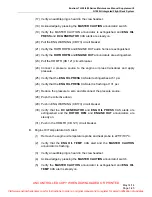
Page 62: ...hat the MASTER CAUTION EMERG BUS DISP BACKUP annunciators illuminate and then extinguish after a few seconds 7 Verify that the ENG CHIP MAIN XMSN CHIP and TAIL CHIP CAS alerts are flashing 8 Verify an audible ping is heard in the crew headset 9 Push in FIRE DETECT CB29 circuit breaker 10 Press and hold the MASTER CAUTION annunciator switch for greater than four seconds 11 Verify that the ENG CHIP ...

Page 63: ... extinguishes at 51 psi 26 Verify that the ENG OIL PRESS CAS alert is flashing at 131 psi 27 Reduce the pressure to zero and disconnect the pressure source 28 Push the collective down 29 Push in ENG WARNING CB173 circuit breaker 30 Verify that the DC GENERATOR and ENG OIL PRESS CAS alerts are extinguished and the ROTOR RPM and ENGINE OUT annunciators are steady on 31 Push in the HR MTR CB 121 circ...

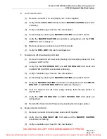
Page 64: ...he MASTER CAUTION annunciator is extinguished and MAIN XMSN HOT CAS alert is steady on 6 Cool the engine oil temperature probe to 212 F 100 C 7 Verify the MAIN XMSN HOT CAS alert is extinguished 8 Reinstall the transmission oil temperature probe D Main Rotor Transmission Pressure CAS Alert 1 Pull XMSN PUMP CB71 circuit breaker 2 Verify that the MAIN XMSN PRESS CAS alert and the MASTER CAUTION annu...

Page 65: ...bes to 248 F 120 C 2 Verify that the FWD DR BRG HOT and AFT DR BRG HOT CAS alerts and the MASTER CAUTION annunciator is flashing 3 Verify an audible ping is heard in the crew headset 4 Acknowledge by pressing the MASTER CAUTION annunciator switch 5 Verify the MASTER CAUTION annunciator is extinguished and the FWD DR BRG HOT and AFT DR BRG HOT CAS alerts are steady on 6 Cool the forward and aft low...

Page 66: ...annunciator switch 5 Verify the MASTER CAUTION annunciator is extinguished and FUEL FILTER CAS alert is steady on 6 Remove jumper and reconnect J68 connector 7 Verify the FUEL FILTER CAS alert is extinguished I Air Frame Fuel Filter CAS Alert Optional Equipment 1 Press and hold the test button on the external fuel filter assembly 2 Verify that the A F FUEL FILTER CAS alert and the MASTER CAUTION a...

Page 67: ...COMPARE and TOT MISCOMPARE CAS alerts are extinguished K TOT Exceedance CAS Alert 1 Drive TOT indication to 1 702 F 928 C using the TOT Calibration Check reference the TH 28 480 Series Maintenance Manual paragraph 7 45 2 Verify that the TOT EXCEEDANCE CAS alert and the MASTER CAUTION annunciator is flashing 3 Verify an audible ping is heard in the crew headset 4 Acknowledge by pressing the MASTER ...

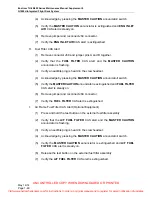
Page 68: ...AN CB156 circuit breaker 2 Verify that the MFD FAN CAS alert and the MASTER CAUTION annunciator is flashing 3 Verify an audible ping is heard in the crew headset 4 Acknowledge by pressing the MASTER CAUTION annunciator switch 5 Verify the MASTER CAUTION annunciator is extinguished and MFD FAN CAS alert is steady on 6 Push in MFD FAN CB156 circuit breaker 7 Verify the MFD FAN CAS alert is extinguis...

Page 69: ...ator switch 15 Verify the MASTER CAUTION annunciator is extinguished and AVI FAN FAIL CAS alert is steady on 16 Push in AVIONIC CF CB154 circuit breaker 17 Verify the AVI FAN FAIL CAS alert is extinguished 18 Push in IAU 1 CB148 circuit breaker O Landing Light On CAS Message 1 Position the LDG LT switch SW107 to ON 2 Verify that the LDG LIGHT ON CAS message is displayed 3 Position the LDG LT switc...

Page 70: ...Engine Anti Ice CAS Message 1 Turn the Anti Ice switch to the ON position 2 Verify that the ENG ANTI ICE CAS message is displayed 3 Turn the Anti Ice switch to the OFF position 4 Verify that the ENG ANTI ICE CAS message is extinguished Visit www enstromhelicopter com for instructions to order an original manual and to register for email notification of updates ...

Page 71: ...ing Diagrams G1000H Interface Diagram Reference P N 4220650 1 P N 4220650 3 Power Distribution 1 1 1 9 G1000H Interface 1 2 1 10 Case Bonding and Grounding 1 3 1 11 Audio Panel 1 4 1 4 Interior Lighting 1 5 1 12 Exterior Lighting 1 6 1 6 Hour Meter 1 7 1 7 Day Night Annunciator Dimmer 1 8 1 8 Visit www enstromhelicopter com for instructions to order an original manual and to register for email not...

Page 72: ...H 28 480 Series Maintenance Manual Supplement 8 G1000H Integrated Flight Deck System May 14 14 Page 1 54 INTENTIONALLY LEFT BLANK Visit www enstromhelicopter com for instructions to order an original manual and to register for email notification of updates ...

Page 73: ...pplement 8 G1000H Integrated Flight Deck System Diagram 1 1 G1000H Power Distribution Interface Ref 4192805 1 Rev A Sheet 1 of 2 Rev 1 Jan 25 18 Page 1 55 1 56 Blank Visit www enstromhelicopter com for instructions to order an original manual and to register for email notification of updates ...

Page 74: ...UNCONTROLLED COPY WHEN DOWNLOADED OR PRINTED Visit www enstromhelicopter com for instructions to order an original manual and to register for email notification of updates ...

Page 75: ...pplement 8 G1000H Integrated Flight Deck System Diagram 1 1 G1000H Power Distribution Interface Ref 4192805 1 Rev A Sheet 2 of 2 Rev 1 Jan 25 18 Page 1 57 1 58 Blank Visit www enstromhelicopter com for instructions to order an original manual and to register for email notification of updates ...

Page 76: ...UNCONTROLLED COPY WHEN DOWNLOADED OR PRINTED Visit www enstromhelicopter com for instructions to order an original manual and to register for email notification of updates ...

Page 77: ...Manual Supplement 8 G1000H Integrated Flight Deck System Diagram 1 2 G1000H Interface Ref 4192801 1 Rev A Sheet 1 of 10 Rev 1 Jan 25 18 Page 1 59 1 60 Blank Visit www enstromhelicopter com for instructions to order an original manual and to register for email notification of updates ...

Page 78: ...UNCONTROLLED COPY WHEN DOWNLOADED OR PRINTED Visit www enstromhelicopter com for instructions to order an original manual and to register for email notification of updates ...

Page 79: ...Manual Supplement 8 G1000H Integrated Flight Deck System Diagram 1 2 G1000H Interface Ref 4192801 1 Rev A Sheet 2 of 10 Rev 1 Jan 25 18 Page 1 61 1 62 Blank Visit www enstromhelicopter com for instructions to order an original manual and to register for email notification of updates ...

Page 80: ...UNCONTROLLED COPY WHEN DOWNLOADED OR PRINTED Visit www enstromhelicopter com for instructions to order an original manual and to register for email notification of updates ...

Page 81: ...Manual Supplement 8 G1000H Integrated Flight Deck System Diagram 1 2 G1000H Interface Ref 4192801 1 Rev A Sheet 3 of 10 Rev 1 Jan 25 18 Page 1 63 1 64 Blank Visit www enstromhelicopter com for instructions to order an original manual and to register for email notification of updates ...

Page 82: ...UNCONTROLLED COPY WHEN DOWNLOADED OR PRINTED Visit www enstromhelicopter com for instructions to order an original manual and to register for email notification of updates ...

Page 83: ...Manual Supplement 8 G1000H Integrated Flight Deck System Diagram 1 2 G1000H Interface Ref 4192801 1 Rev A Sheet 4 of 10 Rev 1 Jan 25 18 Page 1 65 1 66 Blank Visit www enstromhelicopter com for instructions to order an original manual and to register for email notification of updates ...

Page 84: ...UNCONTROLLED COPY WHEN DOWNLOADED OR PRINTED Visit www enstromhelicopter com for instructions to order an original manual and to register for email notification of updates ...

Page 85: ...Manual Supplement 8 G1000H Integrated Flight Deck System Diagram 1 2 G1000H Interface Ref 4192801 1 Rev A Sheet 5 of 10 Rev 1 Jan 25 18 Page 1 67 1 68 Blank Visit www enstromhelicopter com for instructions to order an original manual and to register for email notification of updates ...

Page 86: ...UNCONTROLLED COPY WHEN DOWNLOADED OR PRINTED Visit www enstromhelicopter com for instructions to order an original manual and to register for email notification of updates ...

Page 87: ...Manual Supplement 8 G1000H Integrated Flight Deck System Diagram 1 2 G1000H Interface Ref 4192801 1 Rev A Sheet 6 of 10 Rev 1 Jan 25 18 Page 1 69 1 70 Blank Visit www enstromhelicopter com for instructions to order an original manual and to register for email notification of updates ...

Page 88: ...UNCONTROLLED COPY WHEN DOWNLOADED OR PRINTED Visit www enstromhelicopter com for instructions to order an original manual and to register for email notification of updates ...

Page 89: ...Manual Supplement 8 G1000H Integrated Flight Deck System Diagram 1 2 G1000H Interface Ref 4192801 1 Rev A Sheet 7 of 10 Rev 1 Jan 25 18 Page 1 71 1 72 Blank Visit www enstromhelicopter com for instructions to order an original manual and to register for email notification of updates ...

Page 90: ...UNCONTROLLED COPY WHEN DOWNLOADED OR PRINTED Visit www enstromhelicopter com for instructions to order an original manual and to register for email notification of updates ...

Page 91: ...Manual Supplement 8 G1000H Integrated Flight Deck System Diagram 1 2 G1000H Interface Ref 4192801 1 Rev A Sheet 8 of 10 Rev 1 Jan 25 18 Page 1 73 1 74 Blank Visit www enstromhelicopter com for instructions to order an original manual and to register for email notification of updates ...

Page 92: ...UNCONTROLLED COPY WHEN DOWNLOADED OR PRINTED Visit www enstromhelicopter com for instructions to order an original manual and to register for email notification of updates ...

Page 93: ...Manual Supplement 8 G1000H Integrated Flight Deck System Diagram 1 2 G1000H Interface Ref 4192801 1 Rev A Sheet 9 of 10 Rev 1 Jan 25 18 Page 1 75 1 76 Blank Visit www enstromhelicopter com for instructions to order an original manual and to register for email notification of updates ...

Page 94: ...UNCONTROLLED COPY WHEN DOWNLOADED OR PRINTED Visit www enstromhelicopter com for instructions to order an original manual and to register for email notification of updates ...

Page 95: ...Manual Supplement 8 G1000H Integrated Flight Deck System Diagram 1 2 G1000H Interface Ref 4192801 1 Rev A Sheet 10 of 10 Rev 1 Jan 25 18 Page 1 77 1 78 Blank Visit www enstromhelicopter com for instructions to order an original manual and to register for email notification of updates ...

Page 96: ...UNCONTROLLED COPY WHEN DOWNLOADED OR PRINTED Visit www enstromhelicopter com for instructions to order an original manual and to register for email notification of updates ...

Page 97: ...Manual Supplement 8 G1000H Integrated Flight Deck System Diagram 1 3 G1000H Case Bonding and Grounding Interface Sheet 1 of 2 May 14 14 Page 1 79 1 80 Blank Visit www enstromhelicopter com for instructions to order an original manual and to register for email notification of updates ...

Page 98: ...UNCONTROLLED COPY WHEN DOWNLOADED OR PRINTED Visit www enstromhelicopter com for instructions to order an original manual and to register for email notification of updates ...

Page 99: ...Manual Supplement 8 G1000H Integrated Flight Deck System Diagram 1 3 G1000H Case Bonding and Grounding Interface Sheet 2 of 2 May 14 14 Page 1 81 1 82 Blank Visit www enstromhelicopter com for instructions to order an original manual and to register for email notification of updates ...

Page 100: ...UNCONTROLLED COPY WHEN DOWNLOADED OR PRINTED Visit www enstromhelicopter com for instructions to order an original manual and to register for email notification of updates ...

Page 101: ...l Supplement 8 G1000H Integrated Flight Deck System Diagram 1 4 G1000H Audio Panel Interface Ref 4192807 1 Rev A Sheet 1 of 2 Rev 1 Jan 25 18 Page 1 83 1 84 Blank Visit www enstromhelicopter com for instructions to order an original manual and to register for email notification of updates ...

Page 102: ...UNCONTROLLED COPY WHEN DOWNLOADED OR PRINTED Visit www enstromhelicopter com for instructions to order an original manual and to register for email notification of updates ...

Page 103: ...nce Manual Supplement 8 G1000H Integrated Flight Deck System Diagram 1 4 G1000H Audio Panel Interface Ref 4192807 3 Rev Sheet 2 of 2 Rev 1 Jan 25 18 1 85 Visit www enstromhelicopter com for instructions to order an original manual and to register for email notification of updates ...

Page 104: ... TH 28 480 Series Maintenance Manual Supplement 8 G1000H Integrated Flight Deck System May 14 14 1 86 INTENTIONALLY LEFT BLANK Visit www enstromhelicopter com for instructions to order an original manual and to register for email notification of updates ...

Page 105: ...anual Supplement 8 G1000H Integrated Flight Deck System Diagram 1 5 G1000H Interior Lighting Interface Ref 4192808 1 Rev Rev 1 Jan 25 18 Page 1 87 1 88 Blank Visit www enstromhelicopter com for instructions to order an original manual and to register for email notification of updates ...

Page 106: ...UNCONTROLLED COPY WHEN DOWNLOADED OR PRINTED Visit www enstromhelicopter com for instructions to order an original manual and to register for email notification of updates ...

Page 107: ...nual Supplement 8 G1000H Integrated Flight Deck System Diagram 1 6 G1000H Exterior Lighting Interface Ref 4192513 17 Rev G Rev 1 Jan 25 18 Page 1 89 1 90 Blank Visit www enstromhelicopter com for instructions to order an original manual and to register for email notification of updates ...

Page 108: ...UNCONTROLLED COPY WHEN DOWNLOADED OR PRINTED Visit www enstromhelicopter com for instructions to order an original manual and to register for email notification of updates ...

Page 109: ...ance Manual Supplement 8 G1000H Integrated Flight Deck System Diagram 1 7 G1000H Hour Meter Interface Ref 4192508 53 55 Rev N Rev 1 Jan 25 18 Page 1 91 Visit www enstromhelicopter com for instructions to order an original manual and to register for email notification of updates ...

Page 110: ...H 28 480 Series Maintenance Manual Supplement 8 G1000H Integrated Flight Deck System May 14 14 Page 1 92 INTENTIONALLY LEFT BLANK Visit www enstromhelicopter com for instructions to order an original manual and to register for email notification of updates ...

Page 111: ...nual Supplement 8 G1000H Integrated Flight Deck System Diagram 1 8 G1000H Day Night Annunciator Dimmer Interface Ref 4192809 1 Rev A Rev 1 Jan 25 18 Page 1 93 Visit www enstromhelicopter com for instructions to order an original manual and to register for email notification of updates ...

Page 112: ...H 28 480 Series Maintenance Manual Supplement 8 G1000H Integrated Flight Deck System May 14 14 Page 1 94 INTENTIONALLY LEFT BLANK Visit www enstromhelicopter com for instructions to order an original manual and to register for email notification of updates ...

Page 113: ...pplement 8 G1000H Integrated Flight Deck System Diagram 1 9 G1000H Power Distribution Interface Ref 4192805 1 Rev B Sheet 1 of 2 Rev 1 Jan 25 18 Page 1 95 1 96 Blank Visit www enstromhelicopter com for instructions to order an original manual and to register for email notification of updates ...

Page 114: ...UNCONTROLLED COPY WHEN DOWNLOADED OR PRINTED Visit www enstromhelicopter com for instructions to order an original manual and to register for email notification of updates ...

Page 115: ...pplement 8 G1000H Integrated Flight Deck System Diagram 1 9 G1000H Power Distribution Interface Ref 4192805 1 Rev B Sheet 2 of 2 Rev 1 Jan 25 18 Page 1 97 1 98 Blank Visit www enstromhelicopter com for instructions to order an original manual and to register for email notification of updates ...

Page 116: ...UNCONTROLLED COPY WHEN DOWNLOADED OR PRINTED Visit www enstromhelicopter com for instructions to order an original manual and to register for email notification of updates ...

Page 117: ...anual Supplement 8 G1000H Integrated Flight Deck System Diagram 1 10 G1000H Interface Ref 4192801 3 Rev A Sheet 1 of 10 Rev 1 Jan 25 18 Page 1 99 1 100 Blank Visit www enstromhelicopter com for instructions to order an original manual and to register for email notification of updates ...

Page 118: ...UNCONTROLLED COPY WHEN DOWNLOADED OR PRINTED Visit www enstromhelicopter com for instructions to order an original manual and to register for email notification of updates ...

Page 119: ...anual Supplement 8 G1000H Integrated Flight Deck System Diagram 1 10 G1000H Interface Ref 4192801 3 Rev A Sheet 2 of 10 Rev 1 Jan 25 18 Page 1 101 1 102 Blank Visit www enstromhelicopter com for instructions to order an original manual and to register for email notification of updates ...

Page 120: ...UNCONTROLLED COPY WHEN DOWNLOADED OR PRINTED Visit www enstromhelicopter com for instructions to order an original manual and to register for email notification of updates ...

Page 121: ...anual Supplement 8 G1000H Integrated Flight Deck System Diagram 1 10 G1000H Interface Ref 4192801 3 Rev A Sheet 3 of 10 Rev 1 Jan 25 18 Page 1 103 1 104 Blank Visit www enstromhelicopter com for instructions to order an original manual and to register for email notification of updates ...

Page 122: ...UNCONTROLLED COPY WHEN DOWNLOADED OR PRINTED Visit www enstromhelicopter com for instructions to order an original manual and to register for email notification of updates ...

Page 123: ...anual Supplement 8 G1000H Integrated Flight Deck System Diagram 1 10 G1000H Interface Ref 4192801 3 Rev A Sheet 4 of 10 Rev 1 Jan 25 18 Page 1 105 1 106 Blank Visit www enstromhelicopter com for instructions to order an original manual and to register for email notification of updates ...

Page 124: ...UNCONTROLLED COPY WHEN DOWNLOADED OR PRINTED Visit www enstromhelicopter com for instructions to order an original manual and to register for email notification of updates ...

Page 125: ...anual Supplement 8 G1000H Integrated Flight Deck System Diagram 1 10 G1000H Interface Ref 4192801 3 Rev A Sheet 5 of 10 Rev 1 Jan 25 18 Page 1 107 1 108 Blank Visit www enstromhelicopter com for instructions to order an original manual and to register for email notification of updates ...

Page 126: ...UNCONTROLLED COPY WHEN DOWNLOADED OR PRINTED Visit www enstromhelicopter com for instructions to order an original manual and to register for email notification of updates ...

Page 127: ...anual Supplement 8 G1000H Integrated Flight Deck System Diagram 1 10 G1000H Interface Ref 4192801 3 Rev A Sheet 6 of 10 Rev 1 Jan 25 18 Page 1 109 1 110 Blank Visit www enstromhelicopter com for instructions to order an original manual and to register for email notification of updates ...

Page 128: ...UNCONTROLLED COPY WHEN DOWNLOADED OR PRINTED Visit www enstromhelicopter com for instructions to order an original manual and to register for email notification of updates ...

Page 129: ...anual Supplement 8 G1000H Integrated Flight Deck System Diagram 1 10 G1000H Interface Ref 4192801 3 Rev A Sheet 7 of 10 Rev 1 Jan 25 18 Page 1 111 1 112 Blank Visit www enstromhelicopter com for instructions to order an original manual and to register for email notification of updates ...

Page 130: ...UNCONTROLLED COPY WHEN DOWNLOADED OR PRINTED Visit www enstromhelicopter com for instructions to order an original manual and to register for email notification of updates ...

Page 131: ...anual Supplement 8 G1000H Integrated Flight Deck System Diagram 1 10 G1000H Interface Ref 4192801 3 Rev A Sheet 8 of 10 Rev 1 Jan 25 18 Page 1 113 1 114 Blank Visit www enstromhelicopter com for instructions to order an original manual and to register for email notification of updates ...

Page 132: ...UNCONTROLLED COPY WHEN DOWNLOADED OR PRINTED Visit www enstromhelicopter com for instructions to order an original manual and to register for email notification of updates ...

Page 133: ...anual Supplement 8 G1000H Integrated Flight Deck System Diagram 1 10 G1000H Interface Ref 4192801 3 Rev A Sheet 9 of 10 Rev 1 Jan 25 18 Page 1 115 1 116 Blank Visit www enstromhelicopter com for instructions to order an original manual and to register for email notification of updates ...

Page 134: ...UNCONTROLLED COPY WHEN DOWNLOADED OR PRINTED Visit www enstromhelicopter com for instructions to order an original manual and to register for email notification of updates ...

Page 135: ...nual Supplement 8 G1000H Integrated Flight Deck System Diagram 1 10 G1000H Interface Ref 4192801 3 Rev A Sheet 10 of 10 Rev 1 Jan 25 18 Page 1 117 1 118 Blank Visit www enstromhelicopter com for instructions to order an original manual and to register for email notification of updates ...

Page 136: ...UNCONTROLLED COPY WHEN DOWNLOADED OR PRINTED Visit www enstromhelicopter com for instructions to order an original manual and to register for email notification of updates ...

Page 137: ...e Manual Supplement 8 G1000H Integrated Flight Deck System Diagram 1 11 G1000H Ground Interface Ref 4192806 1 Rev A Rev 1 Jan 25 18 Page 1 119 1 120 Blank Visit www enstromhelicopter com for instructions to order an original manual and to register for email notification of updates ...

Page 138: ...UNCONTROLLED COPY WHEN DOWNLOADED OR PRINTED Visit www enstromhelicopter com for instructions to order an original manual and to register for email notification of updates ...

Page 139: ...ual Supplement 8 G1000H Integrated Flight Deck System Diagram 1 12 G1000H Interior Lighting Interface Ref 4192808 1 Rev A Rev 1 Jan 25 18 Page 1 121 1 122 Blank Visit www enstromhelicopter com for instructions to order an original manual and to register for email notification of updates ...

Page 140: ...UNCONTROLLED COPY WHEN DOWNLOADED OR PRINTED Visit www enstromhelicopter com for instructions to order an original manual and to register for email notification of updates ...

Page 141: ...onders that receive the interrogation thus reducing potential garble on the 1090 MHz band Bottom antenna transmitted interrogations are omni directional using a monopole antenna CI 105 6 Power to the GTS 800 system is provided via the TAS CB162 7 amp circuit breaker located on the left side of the circuit breaker panel Figure 16 Refer to Figure 2 for the GTS 800 unit location and Figure 6 for the ...

Page 142: ...IONS 2 2 Airworthiness Limitations The Airworthiness Limitations Section is FAA approved and specifies inspections and other maintenance required under 14 CFR 43 16 and 91 403 of the Federal Aviation Regulations unless an alternative program has been FAA approved Visit www enstromhelicopter com for instructions to order an original manual and to register for email notification of updates ...

Page 143: ...s The following inspection checklist is intended as a guide for 100 hour annual inspections for aircraft operating under normal conditions More frequent inspections may be required should adverse operating conditions be encountered Date Signature Aircraft Registration Number Aircraft Serial Number GTS 800 INITIAL EACH ITEM AFTER ACCOMPLISHMENT Inspect the following items every 100 hours or annuall...

Page 144: ...t to remove them C Disengage the QMA coax connectors by pulling back firmly on the outer sleeve of the QMA plug away from the jack connector This will disengage the locking mechanism that secures the plug connector to the jack connector Pulling on or disengaging the QMA connectors in any other way is not recommended and may cause damage to both the connectors and coaxial cable D Loosen the unit ho...

Page 145: ...nformation will be improperly displayed E Remove the cable tie or other similar device from the TAS circuit breaker stem and push the stem in to set the circuit breaker F Perform the GTS 800 checkout procedure in accordance with Paragraph 3 11 of the GTS 8XX GPA 65 Installation Manual Figure 30 GTS 800 Installation and Removal Visit www enstromhelicopter com for instructions to order an original m...

Page 146: ...H 28 480 Series Maintenance Manual Supplement 8 G1000H Integrated Flight Deck System May 14 14 Page 2 6 INTENTIONALLY LEFT BLANK Visit www enstromhelicopter com for instructions to order an original manual and to register for email notification of updates ...

Page 147: ...80 Series Maintenance Manual Supplement 8 G1000H Integrated Flight Deck System May 14 14 Page 2 7 SECTION 5 ELECTRICAL WIRING DIAGRAMS Visit www enstromhelicopter com for instructions to order an original manual and to register for email notification of updates ...

Page 148: ...H 28 480 Series Maintenance Manual Supplement 8 G1000H Integrated Flight Deck System May 14 14 Page 2 8 INTENTIONALLY LEFT BLANK Visit www enstromhelicopter com for instructions to order an original manual and to register for email notification of updates ...

Page 149: ...e Manual Supplement 8 G1000H Integrated Flight Deck System Diagram 2 1 GTS 800 Traffic Advisory System Interface Sheet 1 of 2 May 14 14 Page 2 9 2 10 Blank Visit www enstromhelicopter com for instructions to order an original manual and to register for email notification of updates ...

Page 150: ...UNCONTROLLED COPY WHEN DOWNLOADED OR PRINTED Visit www enstromhelicopter com for instructions to order an original manual and to register for email notification of updates ...

Page 151: ... Manual Supplement 8 G1000H Integrated Flight Deck System Diagram 2 1 GTS 800 Traffic Advisory System Interface Sheet 2 of 2 May 14 14 Page 2 11 2 12 Blank Visit www enstromhelicopter com for instructions to order an original manual and to register for email notification of updates ...

Page 152: ...UNCONTROLLED COPY WHEN DOWNLOADED OR PRINTED Visit www enstromhelicopter com for instructions to order an original manual and to register for email notification of updates ...

Page 153: ... Refer to Figure 4 for the GDL 69AH unit location and Figure 6 for the antenna location Refer to 28 AC 062 Rotorcraft Flight Manual Supplement for GDL 69AH operation NOTE For information regarding the GMA 350H audio panel refer to either the GMA 350H electrical schematic Diagram 1 4 the TH 28 480 Series Maintenance Manual Supplement 5 or 28 AC 051 Rotorcraft Flight Manual Supplement for GMA 350H o...

Page 154: ...IONS 3 2 Airworthiness Limitations The Airworthiness Limitations Section is FAA approved and specifies inspections and other maintenance required under 14 CFR 43 16 and 91 403 of the Federal Aviation Regulations unless an alternative program has been FAA approved Visit www enstromhelicopter com for instructions to order an original manual and to register for email notification of updates ...

Page 155: ...Inspections The following inspection checklist is intended as a guide for 100 hour annual inspections for aircraft operating under normal conditions More frequent inspections may be required should adverse operating conditions be encountered Date Signature Aircraft Registration Number Aircraft Serial Number GDL 69AH XM Weather Receiver INITIAL EACH ITEM AFTER ACCOMPLISHMENT Inspect the following i...

Page 156: ...s by installing a cable tie or other similar device around the circuit breaker stem B Access the GDL 69AH by removing the PFD para 1 5 1 2 C Loosen the install screw D Pull the GDL outward and up at least 34 inch This disengages and clears the retaining wedges for removal E Remove unit out of the rack 3 4 3 Installation A Inspect rack connectors for damaged pins before installing the unit B Locate...

Page 157: ...Series Maintenance Manual Supplement 8 G1000H Integrated Flight Deck System May 14 14 Page 3 5 Figure 31 GDL 69AH Installation and Removal Visit www enstromhelicopter com for instructions to order an original manual and to register for email notification of updates ...

Page 158: ...H 28 480 Series Maintenance Manual Supplement 8 G1000H Integrated Flight Deck System May 14 14 Page 3 6 INTENTIONALLY LEFT BLANK Visit www enstromhelicopter com for instructions to order an original manual and to register for email notification of updates ...

Page 159: ...80 Series Maintenance Manual Supplement 8 G1000H Integrated Flight Deck System May 14 14 Page 3 7 SECTION 5 ELECTRICAL WIRING DIAGRAMS Visit www enstromhelicopter com for instructions to order an original manual and to register for email notification of updates ...

Page 160: ...H 28 480 Series Maintenance Manual Supplement 8 G1000H Integrated Flight Deck System May 14 14 Page 3 8 INTENTIONALLY LEFT BLANK Visit www enstromhelicopter com for instructions to order an original manual and to register for email notification of updates ...

Page 161: ...aintenance Manual Supplement 8 G1000H Integrated Flight Deck System Diagram 3 1 GDL69AH Datalink Receiver Interface May 14 14 Page 3 9 3 10 Blank Visit www enstromhelicopter com for instructions to order an original manual and to register for email notification of updates ...

Page 162: ...UNCONTROLLED COPY WHEN DOWNLOADED OR PRINTED Visit www enstromhelicopter com for instructions to order an original manual and to register for email notification of updates ...

Page 163: ...is lost in flight the unit will immediately begin operating on internal battery power Power to the MD302 is provided via the SAM CB175 1 5 amp circuit breaker located on the left side of the circuit breaker panel Figure 16 Refer to Figure 4 for the MD302 unit location Refer to 28 AC 075 Rotorcraft Flight Manual Supplement for MD302 operation 4 1 1 Vendor Publications The following components liste...

Page 164: ...ved and specifies inspections and other maintenance required under 14 CFR 43 16 and 91 403 of the Federal Aviation Regulations unless an alternative program has been FAA approved 4 2 1 Retirement Life The battery module is rated for an estimated life of six 6 years Extreme temperature repeated full depth discharges or other abuse may reduce battery life Visit www enstromhelicopter com for instruct...

Page 165: ...r to Section 5 1 4 Troubleshooting in the MD302 Series Installation Manual and Operating Instructions reference Table 7 and the electrical wiring diagrams in Section 5 of this chapter 4 3 3 Periodic Inspections The following inspection checklist is intended as a guide for aircraft operating under normal conditions More frequent inspections may be required should adverse operating conditions be enc...

Page 166: ...ove the four mounting screws attaching the bezel of the unit to the panel C Pull the unit forward until the end plate is accessible D Disconnect the electrical connector E Disconnect the pitot and static connections F Remove the unit from the instrument panel 4 4 3 Installation A Inspect the connections for damage or corrosion before installing the unit B Connect the pitot and static lines C Conne...

Page 167: ...ess the Configuration Mode menu 1 Press and hold the control knob prior to applying power to the unit After approximately 6 seconds the following message will appear CONTINUE HOLDING TO ENTER CONFIG MODE After a few more seconds the introduction screen will appear and the knob can be released The CONFIGURE MENU will be displayed B Turn the control knob to the BATTERY STORAGE MODE function and pres...

Page 168: ...nance Manual Supplement 8 G1000H Integrated Flight Deck System Rev 1 Jan 25 18 Page 4 6 Figure 33 MD302 Configuration Set Up Reference 4192810 3 Rev A Visit www enstromhelicopter com for instructions to order an original manual and to register for email notification of updates ...

Page 169: ...upplement 8 G1000H Integrated Flight Deck System Rev 1 Jan 25 18 Page 4 7 SECTION 5 ELECTRICAL WIRING DIAGRAMS Diagram 4 1 MD302 Electrical Schematic 4192810 3 Rev A Visit www enstromhelicopter com for instructions to order an original manual and to register for email notification of updates ...

Page 170: ...8 480 Series Maintenance Manual Supplement 8 G1000H Integrated Flight Deck System Rev 1 Jan 25 18 Page 4 8 INTENTIONALLY LEFT BLANK Visit www enstromhelicopter com for instructions to order an original manual and to register for email notification of updates ...

Page 171: ...uning mode frequency and distance The KN 63 DME audio is used to identify the DME ground stations being received The KN 63 is powered by the avionics bus and is protected by a 3 amp circuit breaker DME CB36 located on the left side of the circuit breaker panel Figure 16 Power to the KN 63 may also be controlled by a remote DME ON OFF switch located at the bottom of the circuit breaker panel Figure...

Page 172: ...TATIONS 5 2 Airworthiness Limitations The Airworthiness Limitations Section is FAA approved and specifies inspections and other maintenance required under 14 CFR 43 16 and 91 403 of the Federal Aviation Regulations unless an alternative program has been FAA approved Visit www enstromhelicopter com for instructions to order an original manual and to register for email notification of updates ...

Page 173: ...s chapter 5 3 3 Periodic Inspections The following inspection checklist is intended as a guide for aircraft operating under normal conditions More frequent inspections may be required should adverse operating conditions be encountered Date Signature Aircraft Registration Number Aircraft Serial Number KN 63 DME INITIAL EACH ITEM AFTER ACCOMPLISHMENT Inspect the following items every 100 hours or an...

Page 174: ...ice around the circuit breaker stems B Access the KN 63 via the aft baggage box C Remove the eight AN525 screws that secure the cover to the airframe cover not shown in Figure 34 D Disconnect the wire harness connector and antenna cable E Loosen the screw for the hold down clamp F Slide the KN 63 out of the rack 5 4 3 Installation A Install the KN 63 in the mounting rack so the connectors are on t...

Page 175: ...e the rear plate the third screw may be under a tamper seal and the three screws that secure the dust cover 2 Access the audio level adjustment by peeling back the foil tab marked Audio Level through a hole in one of the inner covers G Install the cover to the airframe with eight AN525 screws Figure 34 KN 63 Installation and Removal Visit www enstromhelicopter com for instructions to order an orig...

Page 176: ...upplement 8 G1000H Integrated Flight Deck System Rev 1 Jan 25 18 Page 5 6 SECTION 5 ELECTRICAL WIRING DIAGRAMS Diagram 5 1 KN 63 Electrical Schematic 4192804 1 Rev A Visit www enstromhelicopter com for instructions to order an original manual and to register for email notification of updates ...

Reviews: