


UNCONTROLLED COPY WHEN DOWNLOADED OR PRINTED
Enstrom TH-28/480 Series Maintenance Manual Supplement 8
G1000H Integrated Flight Deck System
Rev. 1, Jan 25/18
Page
1-39
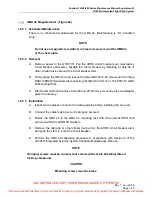
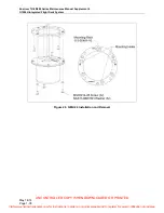
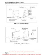
GEA 71H Engine and Airframe (Figure 26)
1.5.7.1 Scheduled
Maintenance
There is no scheduled maintenance for the GEA 71H. Maintenance is “On Condition
Only”.
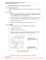
1.5.7.2 Removal
A. Remove power to the GEA 71H. Pull the PFD, EIS 1, and EIS 2 circuit breakers out
(PFD, EIS 1, and EIS 2 circuit breakers are also located on the emergency circuit
breaker panel). Disable the circuit breaker by installing a cable tie or other similar
device around the circuit breaker stem.
B. (GEA 71H #1) Access the GEA 71H #1 by removing the PFD (para. 1.5.1.2).
C. (GEA 71H #2) Access the GEA 71H #2 by removing the pilot side keel access panel
(MM para. 8-14, B).
D. Loosen the install screw.
E. Pull the GEA outward and up at least .34 inch to disengage and clear the retaining
wedges for removal.
F. Remove the unit from the rack.
1.5.7.3 Installation
A. Inspect the rack connectors for damaged pins before installing the unit.
B. Locate the unit on the rack. Lift unit up .34 inch to clear the rack mounting hardware
and align with retaining wedges.
C. Tighten the installation screw to 15 +/- 2 in-lb.
D. Reinstall the PFD (para. 1.5.1.3) or keel access panel (MM para. 8-17, B), as
applicable.
E. Remove the cable tie or other similar device from the PFD, EIS 1, and EIS 2 circuit
breaker stem and push the stem in to set the circuit breaker.
F. Perform the GEA 71 testing and calibration procedures in accordance with Section
6 of the G1000H Integrated Avionics System Standard Maintenance Manual.
Visit www.enstromhelicopter.com for instructions to order an original manual and to register for email notification of updates.


