


Installation and Operation Manual - DustEx
Service and Maintenance
Doc.-ID: COM_OXI_Dust_11022020
15
5.11
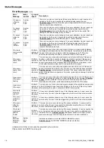
Relay Outputs / Functions and Correlations
The relay contacts are designed for 24V and 1A ~, 1A = (Exception: probe valve)
Relay
Contact
Function
Terminal
System error*
Normally closed
Signals operation-critical errors
X5 (19A/B)
Maintenance
Normally open
System code entered, system in maintenance mode
X5 (18A/B)
Measuring range
Normally open
Closed: Measuring range 1 active
X5 (20A/B)
Probe valve**
Normally open
Triggering of the probe valve
X5 (24A/B)
Limit value
Normally closed
Signals a violation of limit value 1
X5 (21A/B)
Limit value 2
Normally closed
Signals a violation of limit value 2
X5 (22A/B)
Relay outputs and functions
* The relay „system error“ is active also during the heating phase.
** The relay contact for the probe valve is designed for max. 230V and 1A
.
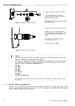
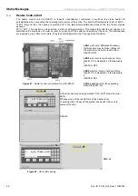
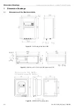
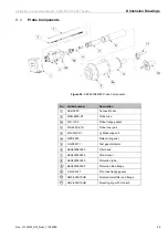
Figure 40
- Relay plate with marked relays and LEDS
LED Mark
Function
A
a
Main probe heater relay
B b Maintenance
C c System
error
D d Limit
O
2
1
E e Measuring
range
F f Limit
O
2
2
G g Probe
valve
H
h
Solenoid valve test gas 1
I
i
Solenoid valve test gas 2
x
Probe heater control