17
compliant and provides at least 30W per port. Using a standard Category 5 patch cable,
simply plug one end into a powered port on your switch or injector and the other end into
DisplayVue™ A15 Ethernet port which can be found at the back of the system, refer to Figure
2.
DisplayVue™ A15 should power up automatically and boot into the operating system.
12VDC AC Adapter power option
If your DisplayVue™ A15 system is configured to be powered by an AC adapter with 12VDC,
simply plug the barrel plug connector from the AC adapter into the barrel jack which can be
found at the back of the system, refer to Figure 2.
DisplayVue™ A15 should power up automatically and boot into the operating system.
Connecting DisplayVue™ A15 to your Network
Power over Ethernet plus (PoE+) power option
If your DisplayVue™ A15 system is configured to use Power over Ethernet plus (PoE+), simply
connect your PoE+ switch or midspan PoE+ injector to your network using a Category 5 patch
cable. The powered CAT5 line from the PoE+ switch or midspan injector will provide data and
power to DisplayVue™ A15.
12VDC AC Adapter power option
If your DisplayVue™ A15 system is configured to use an AC adapter, then connect the
Ethernet port found at the back of the system to your network.
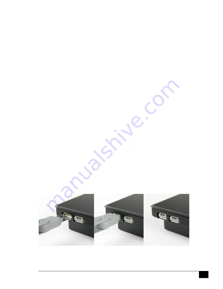
Working with USB Port Blockers (optional)
As an option you can order USB port blockers to prevent unwanted access to the USB ports
on DisplayVue™ A15. A separate key is also available for purchase for authorized users.
These locks are color coded so only like colors will work together. For example only gray keys
will only work with gray locks.
The USB port blocker system is comprised of a “key” and “lock” assembly which plugs into the
USB port. To install the port blockers on your unit, you must install a lock on to the key. Then
insert the lock into the corresponding USB port and release the latch. The lock should remain
in place, inside the USB port.
To remove the lock, simply insert the key without a lock installed into the lock inside the USB
port. Push the latch forward on the key to “grab” the lock and simply pull out.
Figure 8
Installing port blockers in DisplayVue™ A15
Summary of Contents for DisplayVue A15
Page 13: ...13 Mechanical Dimensions Figure 3 Exterior Mechanical Dimensions ...
Page 19: ...19 Notes ...
Page 22: ...22 Notes ...
Page 23: ...23 ...


