background image

EX-5175-EC


ENMET

 Corporation


3.3 Start up 

When the 

EX-5175-EC 

transmitter is first powered up, it goes through a series of momentary screens, which identify 

the instrument model number, serial number and software revision.  After all of the momentary screens have been 
displayed, the instrument arrives at the Main Gas Display showing the gas concentration and unit of measurement. 

Depending on transmitter configuration and calibration condition, the furthest right character in the display may flash a 
letter indicating the instrument status.  See the Section 4.1.2 below. 

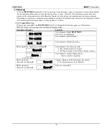
3.3.1 Typical Start Up 

When power is supplied to the 

EX-5175-EC

the S/T will display the following sequence of information: 

N

OTE

:

 Software revision may cause variations of display output. 

Example of Display 

Function 


The instrument: Model 

EX-5175-EC


Note Toxic is not displayed 


The instrument: Serial Number 


The instrument: Software Revision 

IF

 the right most character is a flashing 


The instrument is in Warm-up mode 


This should last about 1 minute 


The Signal Output is held at 4mA during warm-up 


 For 

Toxic 

Gas 

The instrument: Normal Display Mode 
 

Measurement of target Gas 

IF

 the right most 

character is a flashing 

C


The last calibration of the instrument was invalid 


The instrument must be recalibrated 

IF

 the right most 

character is a flashing 

F


There is a sensor fault 


EX-5175 

74-1256 

S/W   X.X 

0ppm  

0ppmW 

0ppmC

0ppmF

Summary of Contents for EX-5175-EC

Page 1: ...ENMET Corporation PO Box 979 Ann Arbor MI 48106 0979 www enmet com Manual Part Number 80003 099 MCN 13 008 11 06 13 EX 5175 EC Sensor Transmitter Manual...

Page 2: ......

Page 3: ...acement 11 6 0 REPLACEMENT PART NUMBERS 12 7 0 WARRANTY 12 List of Figures and Tables Figure 1 EX 5175 EC Features 2 Figure 2 EX 5175 EC Mounting Dimensions 3 Figure 3 Terminal Positions EX 5175 EC Se...

Page 4: ......

Page 5: ...and the contents After the inspection and after you have received written acknowledgment of the damage from the carrier contact ENMET Customer Service for return authorization and further instruction...

Page 6: ...ment maintenance functions The switch locations are indicated by MENU and SELECT A magnetic field pulse is applied by momentarily putting the end of the magnet in proximity to the switch and then remo...

Page 7: ...oosing locations of sensor transmitters Also take into consideration environmental factors when deciding on S T location Avoid locations where the S T may be damaged by liquid immersion excessive heat...

Page 8: ...ct the wires from the controller power supply to the supplied J4 plug then attach to J4 terminal See Figure 3 for locations J4 PLUG TERMINAL TO CONTROLLER WIRING Position Function 1 24 VDC power 2 GND...

Page 9: ...hen power is supplied to the EX 5175 EC the S T will display the following sequence of information NOTE Software revision may cause variations of display output Example of Display Function The instrum...

Page 10: ...on below Display Measurement of the target gas Tap the magnet over the MENU button Display indicates Alarm 1 Set point Tap the magnet over the MENU button Display indicates Alarm 2 Set point Tap the m...

Page 11: ...of target gas Hold the magnet over MENU switch for 2 5 seconds to enter the Maintenance Menu The Power Fault LED will flash Green Red to indicate the EX 5175 EC is in Maintenance Mode To exit the main...

Page 12: ...C transmitters Calibration equipment is available from ENMET Corporation to calibrate the EX 5175 EC sensor transmitters A calibration adapter will have a fitting for the gas cylinder on one side and...

Page 13: ...Figure 4 3 Open the valve to apply the calibration gas to the sensor wait approximately 120 seconds 2 minutes 4 Tap the SELECT switch to perform a Span procedure The display will alternate between th...

Page 14: ...anges digit indicated by underscore cursor The SELECT switch locks underscored digit and moves to next digit See Section 5 2 2 SELECT mA Span MENU SELECT 100 To change mA Span set point Tap the MENU s...

Page 15: ...d Assembly into the sensor housing cover Reassemble the sensor housing Turn On the sensor transmitter After the new sensor has been installed it is suggested to allow the sensor to stabilize for 24 ho...

Page 16: ...edEx Ground If an expedient means of transportation is requested during the warranty period the customer is responsible for the difference between the most economical means and the expedient mode ENME...

Page 17: ...processing delays ENMET charges a one hour minimum billing for all approved repairs with additional time billed to the closest tenth of an hour All instruments sent to ENMET are subject to a minimum...

Page 18: ......

Page 19: ..._____________ Payment Terms COD Check one VISA MasterCard______________________ ________ ________ Card number Expiration Card Code American Express______________________ ________ ________ Card number...

Page 20: ......

Reviews: