


Table of Contents
1.0
I
NTRODUCTION
....................................................................................................................................................... 1
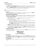
1.1 Unpack ............................................................................................................................................................................... 1
1.2 Check Order ....................................................................................................................................................................... 1
1.3 Serial Numbers .................................................................................................................................................................. 1
2.0
F
EATURES OF THE
EX-5175-EC ............................................................................................................................. 2
3.0
I
NSTALLATION OF THE
EX-5175-EC ........................................................................................................................ 3
3.1 Mounting the EX-5175-EC Enclosure ............................................................................................................................... 3
3.2 Wiring the EX-5175-EC to a Control Unit ........................................................................................................................ 4
3.3 Start up ............................................................................................................................................................................... 5
3.3.1 Typical Start Up .............................................................................................................................................................................. 5
4.0
O
PERATION OF THE
EX-5175-EC ........................................................................................................................... 6
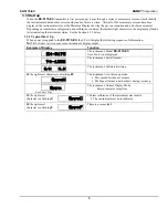
4.1 Normal Display Mode ....................................................................................................................................................... 6
4.1.1 Alarm Conditions
EX-5175-EC
..................................................................................................................................................... 6
5.0
M
AINTENANCE OF THE
EX-5175-EC ....................................................................................................................... 7
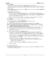
5.1 Maintenance Menu ............................................................................................................................................................ 7
5.2 Calibration of the EX-5175-EC ......................................................................................................................................... 8
5.2.1 Zero Adjust ...................................................................................................................................................................................... 9
5.2.2 Gas Span ......................................................................................................................................................................................... 9
5.2.3 Exit Maintenance Menu .................................................................................................................................................................. 9
5.3 Sensor Replacement......................................................................................................................................................... 11
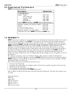
6.0
R
EPLACEMENT
P
ART
N
UMBERS
............................................................................................................................ 12
7.0
WARRANTY ...................................................................................................................................................... 12
List of Figures and Tables
Figure 1: EX-5175-EC Features ................................................................................................................................ 2
Figure 2: EX-5175-EC Mounting Dimensions ............................................................................................................ 3
Figure 3: Terminal Positions EX-5175-EC Sensor/Transmitter ................................................................................. 4
Table 1: EX-5175-EC maintenance Menus Sequence .............................................................................................. 7
Figure 4: Calibration Adapter EX-5175-EC Sensor/Transmitter ................................................................................ 8
Table 2: Examples of S/T ranges, alarm Points and Calibration Gas ....................................................................... 8
Figure 5: EX-5175-EC Maintenance Menu Flow chart ............................................................................................ 10
Figure 6: Sensor Replacement ................................................................................................................................ 11
Reference information:
N
OTE
:
[important information about use of instrument – if not followed may have to redo some steps.]
C
AUTION
:
[affects equipment – if not followed may cause damage to instrument, sensor etc…]
W
ARNING
:
[affects personnel safety – if not followed may cause bodily injury or death.]


