3.5"HDD
1
2
3
4
5
6
7
8
9
10
11
12
13
14
15
16
17
18
19
20
Option
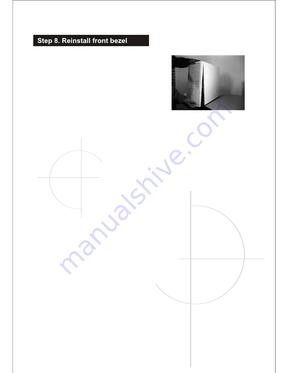
Fig:15
Snap into place, starting with
top snaps. Make sure tabs at top
of bezel are in place in holes at
top of chassis, then push lower
half of bezel into place
Page 1: ...USERMANUAL EN 7230...
Page 2: ...number before proceeding The user manual is set up to correspond to the model number and installation will vary depending on the model Required tools Phillips head screwdriver pliers Photos shown may...
Page 3: ...in housing Fig 5 Snap fan housing back into the chassis Connect fan and speaker wiring to M B as instructed in M B user manual After M B is installed Install 3 5 HDD and FDD floppy A Squeeze tabs on s...
Page 4: ...on the I O plate are punched out matching ports on the M B E Install at an angle first by lining up the I O ports on the M B with I O plate Fig 10 F Once holes are lined up set M B on standoffs or st...
Page 5: ...ng towards back of chassis Use hex screws to fasten side panels in place To replace top cover spread sides as shown in Fig 14 Slide vertically down and make sure slide fasteners guides are properly se...
Page 6: ...Fig 15 Snap into place starting with top snaps Make sure tabs at top of bezel are in place in holes at top of chassis then push lower half of bezel into place...
Page 7: ...3 5 HDD 1 2 3 4 5 6 7 8 9 10 11 12 13 14 15 16 17 18 19 20 Option...
Page 8: ...7230 ONLY 11 5404613 CONTROL CONNECTOR A 12 3132596 POWER SWITCH HOLDER 13 3212514 3 5 EMI CLIP 14 3131467 RUBBER FOOT 15 5404624 CONTROL CONNECTOR B 16 32140541 I O PLATE 17 3406140 FAN 8CM 18 340172...