background image

SET‐UP & OPERATIONS

1.

Install a “

Battery Pack

” into the “

Transceiver Base Station

” as follows:

a.

Open battery compartment by sliding the tab cover located on the outer/front 
of the “

Transceiver Base Station

” upwards.

b.

Insert a “

Battery Pack

” into the compartment so that label is facing upwards 

and the (2) (+/‐) contacts located on the top of the battery are facing away 
from the tab cover.

c.

Close the battery compartment by sliding its tab cover downwards. 

2.

Power on the “

Transceiver Base Station

” by rotating the “

ON/OFF VOL.

” dial located 

on the outer/front of the device to the left. 

NOTE:

When powered on, the 

CONFERENCE

” LED located on the top of the device will flash on then turn off and 

the “

POWER STATUS

” LED located on the outer/left side will turn on and remain 

solid.

*

3.

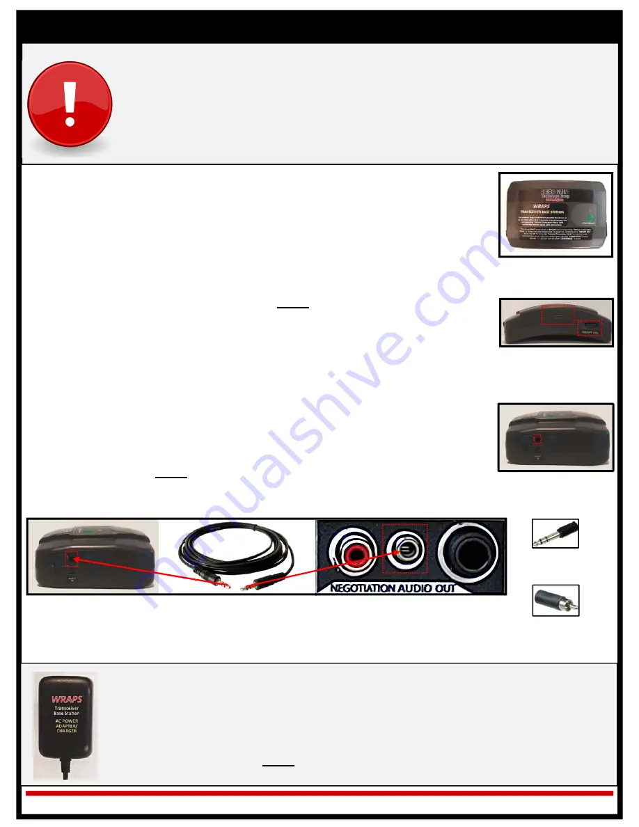
If the WRAPS

System is to be used to allow for operators to wirelessly monitor an 

external audio source, connect the “

Transceiver Base Station

” to the source by using 

the provided “

25 ft. Audio Cable

” as follows:

a.

Insert either 1/8” (3.5mm) plug of the “

25 ft. Audio Cable

” into the “

AUDIO 

IN

” jack located on the outer/right of the “

Transceiver Base Station

.”

b.

Insert the remaining plug of the “

25 ft. Audio Cable

” into any available 1/8” 

(3.5mm) audio out jack located on the external audio source that is to be 
monitored.  

NOTE:

Audio cable adapters have been provided standard to 

support the connection to an external audio source that is only equipped with 
a  ¼” (6.35mm) or RCA/Composite audio out jacks. 

The WRAPS

System’s Transceiver Base Station 

MUST 

be powered on

BEFORE

any of the 

corresponding Remote Transceiver Packs are powered on to allow a link to be 
established!

For optimum range/performance the Transceiver Base Station should be positioned on 
an elevated surface that is centrally located between the operators equipped with 
Remote Transceiver Packs with no/minimal signal path obstructions.

Pg. 5 of 11

Ops Ver. 03/18

Transceiver Base Station

Transceiver Base Station 

Battery Compartment &

“POWER ON/OFF VOL.”

Dial

*

The “

Transceiver Base Station

” may also be powered via an external 120v wall outlet power 

supply as follows:

1.

Insert the pin end of the provided “

Transceiver Base Station AC Power Adapter/Charger

” 

into the power port located on the outer/left of the “

Transceiver Base Station

.”

2.

Insert the plug end of the “

Transceiver Base Station AC Power Adapter/Charger

” into a 

120v electrical outlet. 

NOTE:

If a “

Battery Pack

” is installed into the “

Transceiver Base 

Station

” when it is connected to an external power supply will automatically trickle charge.

Transceiver Base Station 

“AUDIO IN” Jack

Transceiver Base Station Connected to External Audio Source’s  ⅛” (3.5mm) Audio Out Jack via 

25 ft. Audio Cable

⅛” (3.5mm) to 

¼” (6.35mm) 

Adapter 

⅛” (3.5mm) to 

RCA/

Composite 

Adapter

Summary of Contents for ETG-WRAPS-SYS

Page 1: ... instructors to determine where the System fits into his her department s rules regulations policies and procedures Compliance with Local Laws It is the Client s responsibility to ensure the purchase handling and usage of the WRAPS System complies with all local state and federal laws and regulations Product Changes Client understands that ETGI may from time to time change the WRAPS System s speci...

Page 2: ... bay with AC Power Adapter 2 Spare Additional Rechargeable Battery Packs All WRAPS Systems are delivered with a minimum quantity of 2 Remote Transceiver Pack Kits The actual quantity of Remote Transceiver Pack Kits delivered is determined by WRAPS System model purchased Up to 6 Remote Transceiver Packs may be connected to used simultaneously with the WRAPS System s Transceiver Base Station Additio...

Page 3: ...gotiation Audio Channel operators equipped with the Remote Transceiver Packs can wirelessly monitor the audio source i e Negotiation Audio Channel while still having the ability to talk and listen to another Any communications that take place between the operators equipped with the WRAPS System s Remote Transceiver Packs do NOT feedback into the audio source i e Negotiation Audio Channel that is b...

Page 4: ...stage Crisis Negotiations Throw Phone or other communications system equipment that is be monitored by the operators After the Transceiver Base Station has been connected to the desired audio source i e negotiations communications taking place between the Negotiator and subject operators wearing the Remote Transceiver Packs positioned within the Wireless Communications Field Network are now be abl...

Page 5: ...f the Battery Charge Station A C Power Adapter into a 120v wall outlet power supply 4 Insert a Battery Pack into any available charging bay located on the Battery Charge Station checking that battery and bay s contacts are properly aligned 5 Once inserted press the Battery Pack downwards to secure its position within the charging bay NOTE When properly inserted the LED located above the correspond...

Page 6: ...to be monitored NOTE Audio cable adapters have been provided standard to support the connection to an external audio source that is only equipped with a 6 35mm or RCA Composite audio out jacks The WRAPS System s Transceiver Base Station MUST be powered on BEFORE any of the corresponding Remote Transceiver Packs are powered on to allow a link to be established For optimum range performance the Tran...

Page 7: ...d listen to one another set the Transceiver Base Station to Conference operating mode by pressing the device s green CONFERENCE button NOTE The red LED located on the front of the Transceiver Base Station will turn on and remain solid when the device is set to Conference operating mode The WRAPS System s Transceiver Base Station MUST be powered on BEFORE any of the corresponding Remote Transceiver...

Page 8: ...ne of the Headset may be muted One way to mute the Headset microphone is by swiveling the boom microphone s arm upwards to set it to the UP position parallel to the headband The other way to mute the Headset microphone is to press the MIC button located on the outer top of the Remote Transceiver Pack When pressed the MIC button will turn red to indicate the microphone of the connected Headset is m...

Page 9: ...off the Transceiver Base Station rotate the ON OFF VOL located on the outer front of the device to the right until click sound is produced and then remove the Battery Pack from the device NOTE When powered off the device s POWER STATUS LED will turn off To power off a Remote Transceiver Pack press and hold down the device s power on off button for approx 5 seconds then release and then remove the ...

Page 10: ...e Transceiver Packs can communicate with one another When the WRAPS System s Transceiver Base Station is powered on it defaults to Dual Channel operating mode When the Transceiver Base Station is set to Dual Channel operating mode ONLY the Remote Transceiver Packs that are set to the SAME Programming Channel Group either 1 or 2 can communicate with one another To allow ALL Remote Transceiver Packs...

Page 11: ... the 1 Programming Button for approx 5 seconds until its corresponding LED begins to flash on and off then release b While the corresponding LED is flashing on and off press the 1 Programming Button 7 consecutive times NOTE When this is performed the corresponding LED will begin to rapidly flash on off for approx 10 seconds and will then turn off indicating that all the Programming Channel Group 1...

Page 12: ...off the Remote Transceiver Pack by pressing and holding down the device s POWER ON OFF button NOTE When powered off both the Remote Transceiver Belt Pack and the 1 Programming Button LEDs will turn off 5 Repeat steps 3 and 4 to program up to 2 additional Remote Transceiver Packs to Programming Channel Group 1 6 To program a Remote Transceiver Pack to Programming Channel Group 2 follow these steps ...

Reviews: