185
Installation instructions for professionals
6
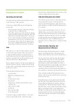
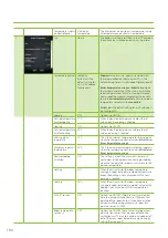
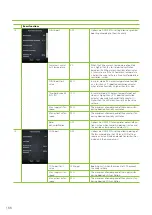
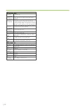
Analog input 1
%RH sensor1
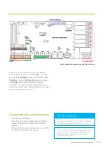
Define the functionality and set the voltage for
the analog inputs 1-6 on the MD motherboard.
AI settings needs to be configured if there are
external sensors connected to the ventilation unit,
besides the two RH% and CO₂ sensors that are
preconfigured.
Analog input 2
%RH sensor 2
Analog input 3
None
Analog input 4
None
Analog input 5
CO2 sensor1
Analog input 6
CO2 sensor 2
7
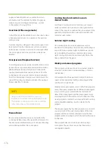
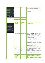
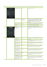
Constant duct pres-
sure control
OFF
Options are ON/OFF.
Air flow setup mode Constant pressure
Selecting
Constant pressure
requires all fan power
settings to be entered as duct pressures, and the
automation will automatically maintain the duct
pressure by varying the fan speeds. Select this set-
ting if you know the required duct pressures for the
different operating modes.
Selecting
Constant speed
will allow the airflow
measurements to be made without the duct pres-
sure control. The measured duct pressures are
shown under the fan speed settings for reference,
and are automatically stored when continuing to
the next setting. After completing all fan speed
settings the constant duct pressure control is auto-
matically activated, and fan speed control will be
automatic according to duct pressures. Use this set-
ting if you don’t know the needed duct pressures
for the different operating modes.
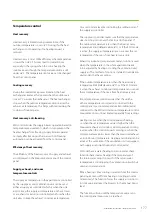
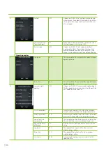
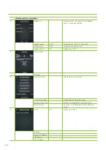
P-band
25
P-band value determines how much the fan speed
will be altered.
I-time
5 s
I-time value determines how quick the change to
the fan speed will be.
DZ
2 Pa
DZ (dead zone) is the deviation in the set duct pressure
where the controller has no effect on the fan speed.
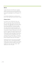
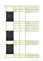
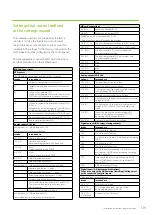
Alarm delay for
supply air duct
pressure
200 s
If pressure deviation is greater than the set alarm
limit, an alarm will be triggered after the delay set
here.
Alarm delay for
extract air duct
pressure
200 s
If pressure deviation is greater than the set alarm
limit, an alarm will be triggered after the delay set
here.
Alarm limit
10 Pa
An alarm is triggered if pressure deviation is greater
than the alarm limit set here.
Summary of Contents for LTR-3 eAir
Page 8: ...8 Kanavaliitännät ulkoilma tuloilma poistoilma jäteilma ...
Page 20: ...20 11 13 9 12 Lisävaruste 1 2 min 10 ...
Page 48: ...48 ...
Page 51: ...51 Ammattilaisen asennusohje ...
Page 52: ...52 LTR 3 eAir Installationsanvisningar för ventilationsaggregat Svenska ...
Page 58: ...58 Kanalanslutningar uteluft tilluft frånluft avluft ...
Page 70: ...70 9 13 15 11 10 14 Extra tillbehör 1 2 min 12 ...
Page 98: ...98 ...
Page 101: ...101 Installationsanvisningar för yrkesfolk ...
Page 102: ...102 Installeringsinstruksjoner for ventilasjonsenheten Norsk LTR 3 eAir ...
Page 108: ...108 Kanalkoblinger utendørsluft tilluft avtrekksluft avkastluft ...
Page 120: ...120 9 13 15 11 10 14 1 2 min 12 ...
Page 148: ...148 ...
Page 151: ...151 Installasjonsinstrukser for fagfolk ...
Page 152: ...152 LTR 3 eAir Installation instructions for the ventilation unit English ...
Page 158: ...158 Duct connections outdoor air supply air extract air exhaust air ...
Page 170: ...170 9 13 15 11 10 14 Extra 1 2 min 12 ...
Page 198: ...198 ...
Page 203: ...203 Koblinger Connections ...
Page 204: ...204 ...
Page 205: ...205 ...
Page 206: ...206 ...
Page 207: ...207 ...
Page 208: ...208 ...
Page 209: ...209 ...
Page 210: ...210 ...
Page 211: ...211 ...
Page 212: ...212 ...
Page 214: ...214 eAir W Periaatekaavio eAir W Principschema eAir W Prinsippskisse eAir W Principle schema ...
Page 215: ...215 ...
Page 218: ...218 ...
Page 219: ...219 ...

